PhotoRobot Control Units - Technical Documentation
The control system is a key component of every robot, so PhotoRobot uses only in-house manufactured control systems. This allows for complete control over their design. Meanwhile, the robot’s controller works optimally with higher level software, on a computer or in the cloud, thanks to PhotoRobot directly designing and producing everything – tailoring components precisely to the processes they perform.
PhotoRobot rigorously manages the API at all levels. The cloud system has an API for easy integration with the customer’s other systems, and the robot’s control unit also features an API for integration with third-party systems. This modern concept allows customers to implement even very complex integrations.
The following table shows the essential characteristics of the latest versions of PhotoRobot’s control systems. The development demonstrates an increase in the range of functions and the computational performance of the control computer (starting with generation 6, which is based on PhotoRobot OS).
PIC32 Family 80
MHz/105 DMIPS
ARM Cortex-A8,
32bit, 1GHz,
2000 MIPS
ARM Cortex-A8,
32bit, 1GHz,
2000 MIPS
ARM Cortex-A8,
32bit, 1GHz,
2000 MIPS
ARM Cortex-A8,
32bit, 1GHz,
2000 MIPS
(SLAVE module)
(for expansion boards)
(on SLAVE modules)
Note: Control systems older than generation 6 no longer meet modern architectural and safety standards. The newer control units are fully backward compatible, so it is not a problem to easily upgrade a PhotoRobot over 10 years old to achieve the highest performance and the latest parameters by simply replacing the control system. New external control units in a 19" rack format (2U) are connected via cables – immediately after connection, the Robot can perform the most advanced functions.
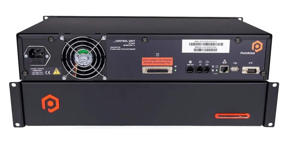
Robot Control Unit (Robot Controller)
The Robot Control Unit (Robot Controller) controls the mechanical movements of the machine.
Multi-Camera Controller (SynchroBox)
The Multi-Camera Controller (SynchroBox) provides precise synchronization of multiple cameras during the “fast spin” rapid photography method.
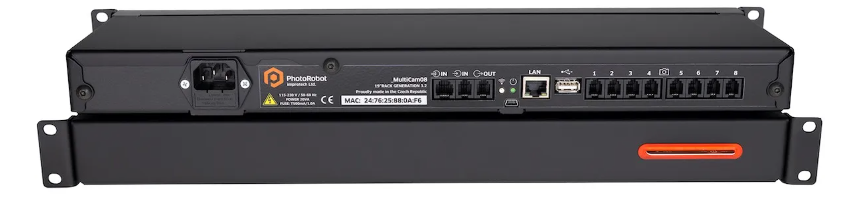
- Note: For technical documentation on the connection and first use of the Multi-Camera Controller (SynchroBox), refer to PhotoRobot SynchroBox Use & Setup.
Laser Controller
The Laser Controller controls 1 - 20 positioning lasers for the accurate placement of objects within the machine’s workspace.

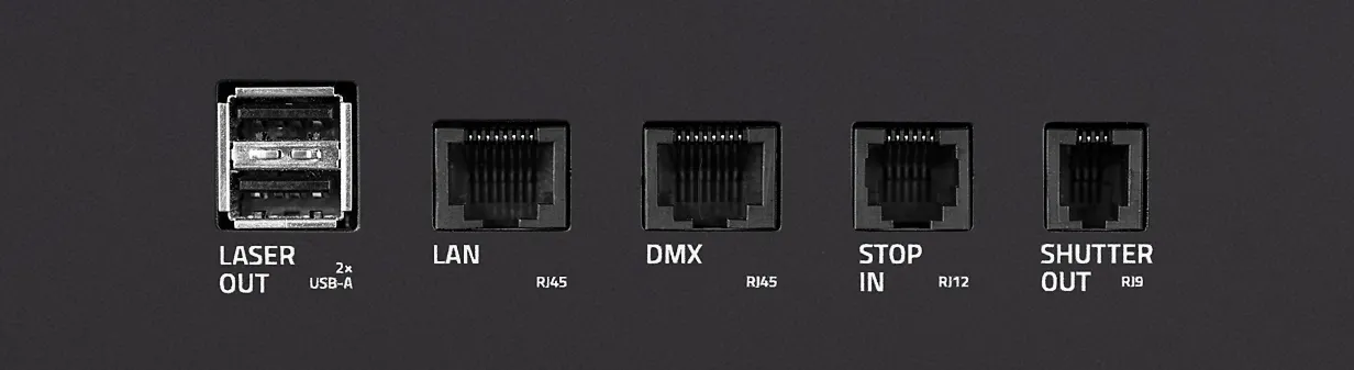
Standardized Outputs
For easy upgrades or servicing, PhotoRobot uses external control units built into a 19” rack cabinet. The unit connects to the robot and peripherals via cabling.
In compact machines (COMPACT series) which require easy mobility, or in multi-axis machines, built-in control units are used. The built-in control unit provides easy access for service or updates, thereby eliminating the need for cabling installation within the studio.
If the machine does not have a built-in control unit, the standalone unit additionally contains connectors to link the control unit to the mechanical parts of the robot.
Main Processor
Since generation 6, PhotoRobot has relied on powerful ARM processors with high clock speeds, ensuring the performance required for advanced control functions.
Operating System
From generation 6 control units, PhotoRobot OS is a Linux-based, real-time operating system that provides excellent performance and flexibility. The built-in web server provides monitoring, diagnostic tools, and basic control movement features.
Optical Position Sensor
On frictionless optical tables, a non-contact optical sensor is used for automatic re-calibration of the machine’s virtual gear ratio with each rotation during operation. This eliminates the need for user calibration (after the initial setup) and ensures exceptionally high accuracy in the placement of the machine’s table, which minimizes the impact of impurities, slippage, etc.
Quadratic Encoder
This component continuously determines the precise position of the machine's glass table. Depending on the machine type and table size, there are approximately 40,000 pulses per table rotation, evaluated 1000 times per second. This arrangement allows the capture of images from precise angles while the machine is in motion, without the need to stop the table. To freeze the motion, a flash from high-power photographic lights with a duration of 1/10,000 s is used – with the robot providing an adjustable advance notification when reaching the defined position.
Absolute Encoder
The absolute encoder is used to accurately determine the position of each machine axis without the need to engage a calibration sensor.
Digital Inputs
These are used to control the unit with an external signal (for example, a foot switch to start a photographic sequence, a motion sensor, etc.). The inputs are galvanically isolated.
Digital Outputs
These outputs are used to control external devices – typically to trigger a camera. The dual output, in this case, allows, for example, the pre-raising of a mirror in SLR cameras with one signal and then a rapid exposure with the other. The outputs are galvanically isolated.
Laser Out
This output is used to control external lasers for the precise positioning of objects on the tables. Units that do not have built-in laser control can use digital outputs in conjunction with an external laser unit or opt for an autonomous laser unit controlled via LAN with its own processor (available in variants with additional inputs and outputs for peripheral connections).
DMX
DMX controls external devices, typically LED photographic lights (adjusting intensity and color). For increased reliability, DMX control is integrated directly into the control unit, significantly reducing the number of potential failure points compared to various USB converters connected to a PC.
USB Output
The USB port is available on the casing of mobile robots (typically the CASE850), allowing the connection of selected external peripherals such as a USB Wi-Fi dongle when a LAN network is unavailable at the installation site. On machines designed for studio use, the USB port is not installed because more reliable and high-performance methods for data exchange are available within the studio environment.
Safety Stop
This feature is provided to connect an emergency stop button, as required by legislative or operational standards.
CAN Bus
An industrial bus used for connecting expansion boards that facilitate control of additional machine axes, specialized accessory equipment, and machine expansion modules.
RS485
An industrial bus used for communication between individual machine components (e.g., sensors), instead of traditional one-to-one cabling. This significantly simplifies the wiring of larger systems.
Connectivity
PhotoRobot control units are interconnected exclusively via a LAN network (USB and similar solutions cannot be reliably used on a larger scale, while LAN-based solutions can cover the needs of a small studio with one robot, same as large companies running more than 200 robotic workspaces in one cluster). A built-in web server (operating on the unit’s IP address) provides access to the unit’s control system (updates, service, monitoring).
It is also possible to locate and manage the control unit using the PhotoRobot Locator application. The PhotoRobot Locator app is integrated directly within PhotoRobot Controls App (CAPP) for the easier search and identification of control units on the network. Ensure you are using the most up-to-date version of CAPP to access this feature.
If external download of the Locator app is required, downloading is also available within PhotoRobot Account Downloads, or directly from App Store for iPhone - PhotoRobot Touch.