
PhotoRobot CASE 850 User Guide
This user and installation guide provides technical instructions for the assembly, connection, and use of the PhotoRobot CASE 850. The information aims to support customers in the initial setup, understanding, and operation of the robot by the customer.
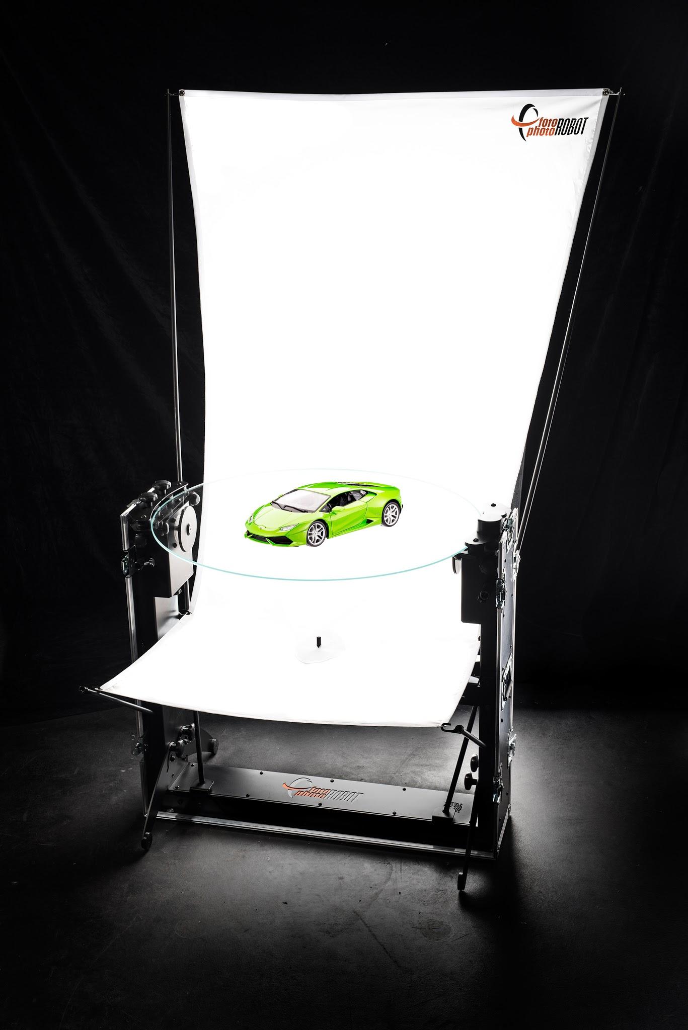
Important: The initial installation of a PhotoRobot system must always be carried out by an authorized PhotoRobot authority. Authorities with authorization to install PhotoRobot are an approved distributor, or a representative of the manufacturer itself.
Note: Always refer to PhotoRobot Safety Information & Instructions before any self-installation, first use, storage, or service of PhotoRobot devices.
1. About the CASE 850
The PhotoRobot CASE aims to set new standards in 360° product photography. It combines mobility, durability, precision and speed. It can be used in the studio or on location. Its unique construction allows you to capture fine-tuned product photographs as well as handle 360 degree image mass production.
Explore the brilliance of the CASE 850 through this comprehensive user guide, beginning with 10 key features that will redefine your automated photography workflows.
- The whole CASE 850 robot fits in an easy to fold & carry case.
- Assembly takes a matter of minutes — around 15.
- The CASE is fast – it makes a full turn in about 2.1 seconds.
- Operate the CASE from a computer with the PhotoRobot Controls app.
- A single app controls the robot, camera, and flash lights together.
- An integrated cross laser ensures precise product positioning.
- The 850 mm glass plate is perfect for pure white background photography.
- Its encoder guarantees peak plate rotation accuracy.
- Foldable legs give the CASE 850 supreme stability.
- An airy construction provides freedom for lighting – light from bottom, top, front, back, or sides.
1.1. Unpacking
Even though the CASE is very durable and ready to transport as a case itself, you might want to keep the original cardboard box we use for shipping. Keeping in mind all the delicate mechanics inside the CASE, the cardboard box might come in handy for possibly rough transport conditions. To be able to reuse the cardboard box and still easily unpack the CASE, please use the following instructions.
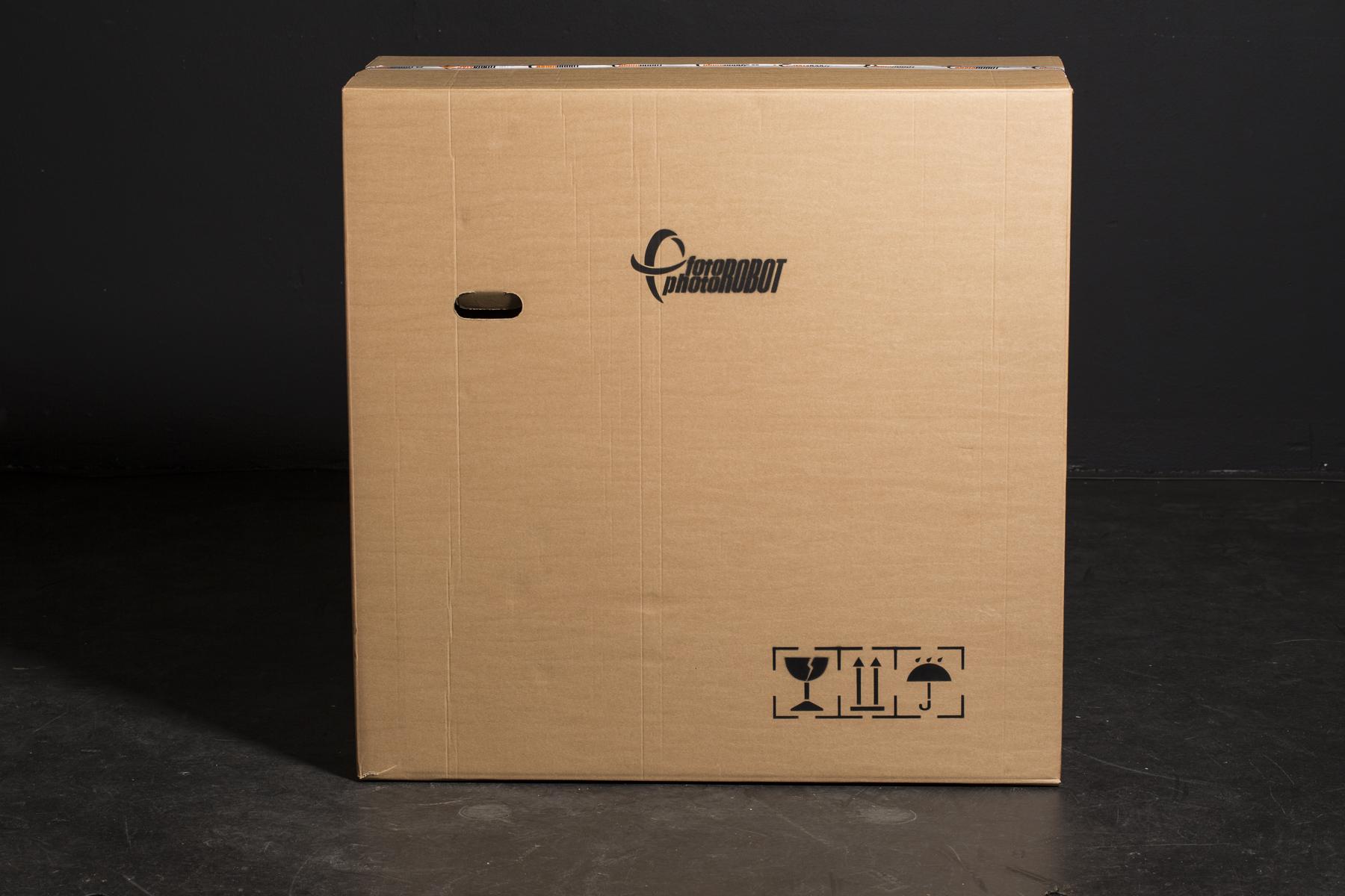
- Place the box on a clean, flat surface.
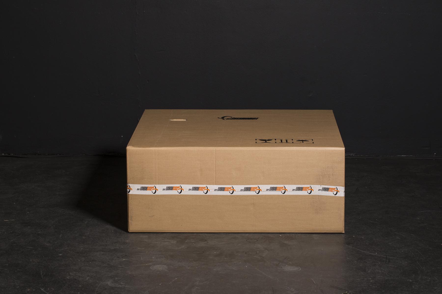
- Lay the box on the side.
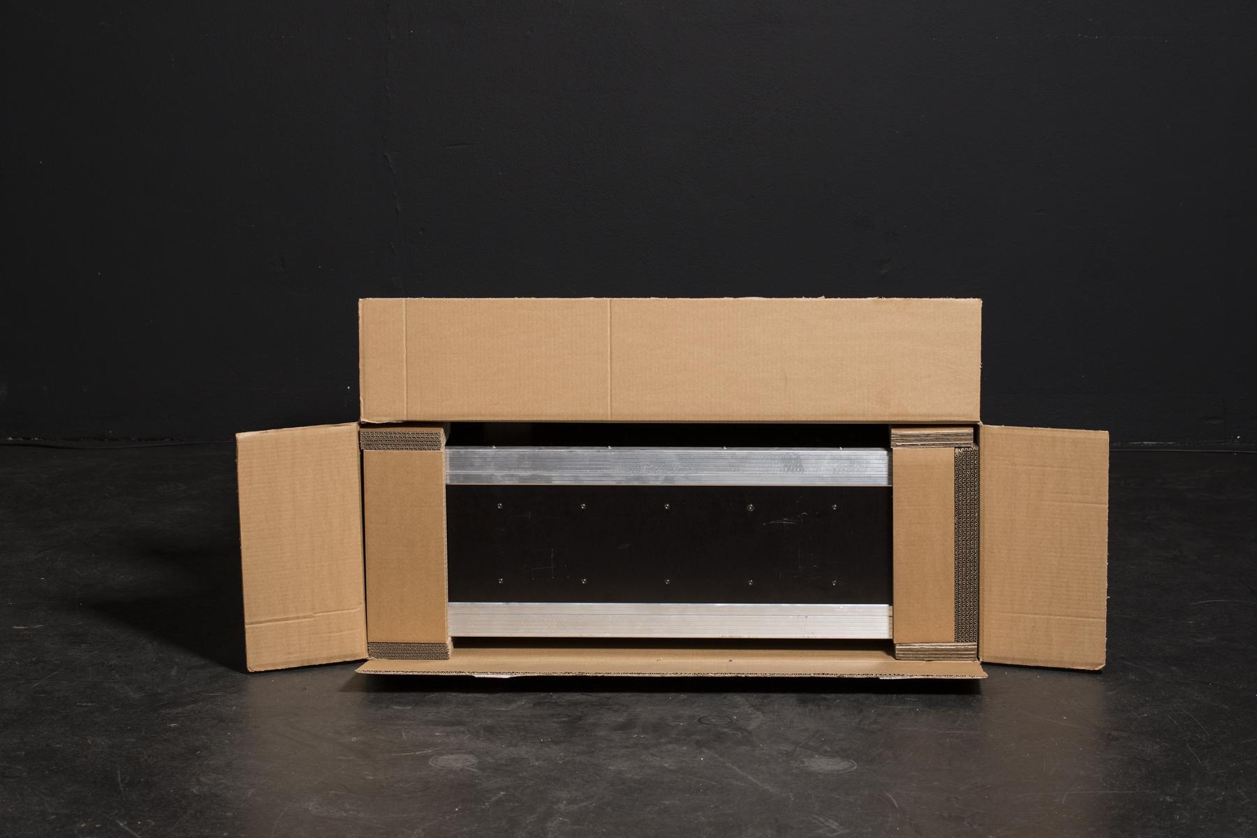
- Cut open the shortest side.
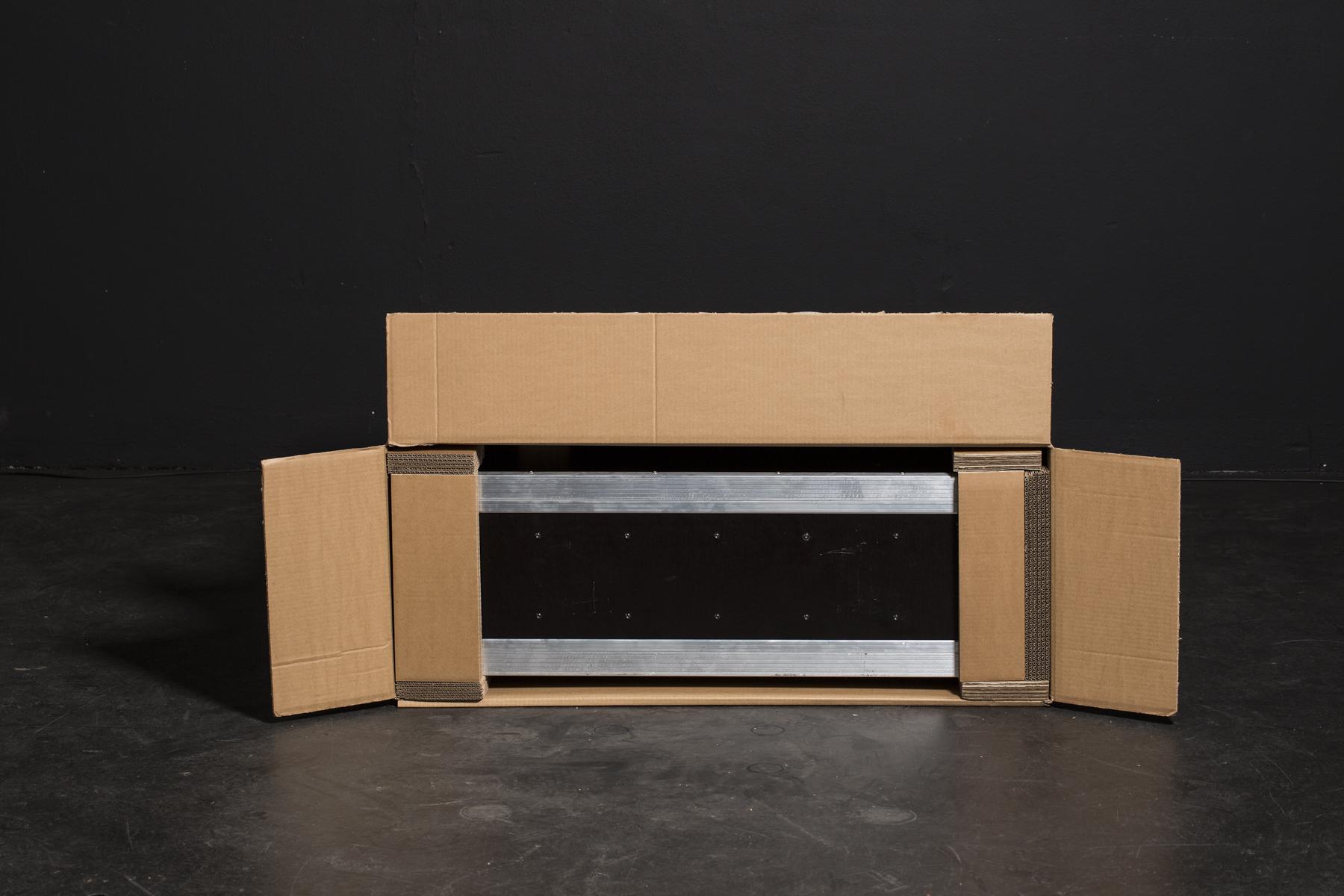
- Slide a long flap under the box.

- Stand the box on the open side, and pull the cardboard off the CASE.
1.2. Packing
To make the CASE as compact and safe to transport as it is, we had to carefully define the right spot for each component to be firmly attached. The following photo instructions will guide you through folding the assembled robot into a one-piece case.
To put the CASE back to the shipping cardboard box, simply reverse steps of chapter 1.1 - Unpacking.
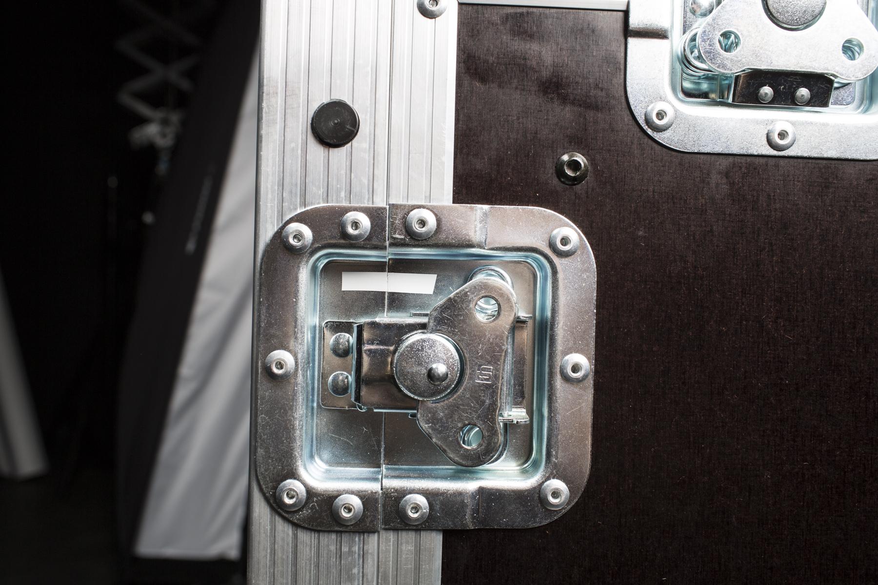
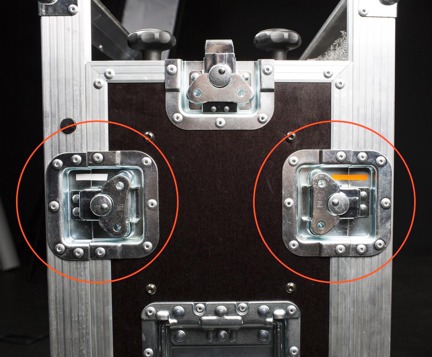
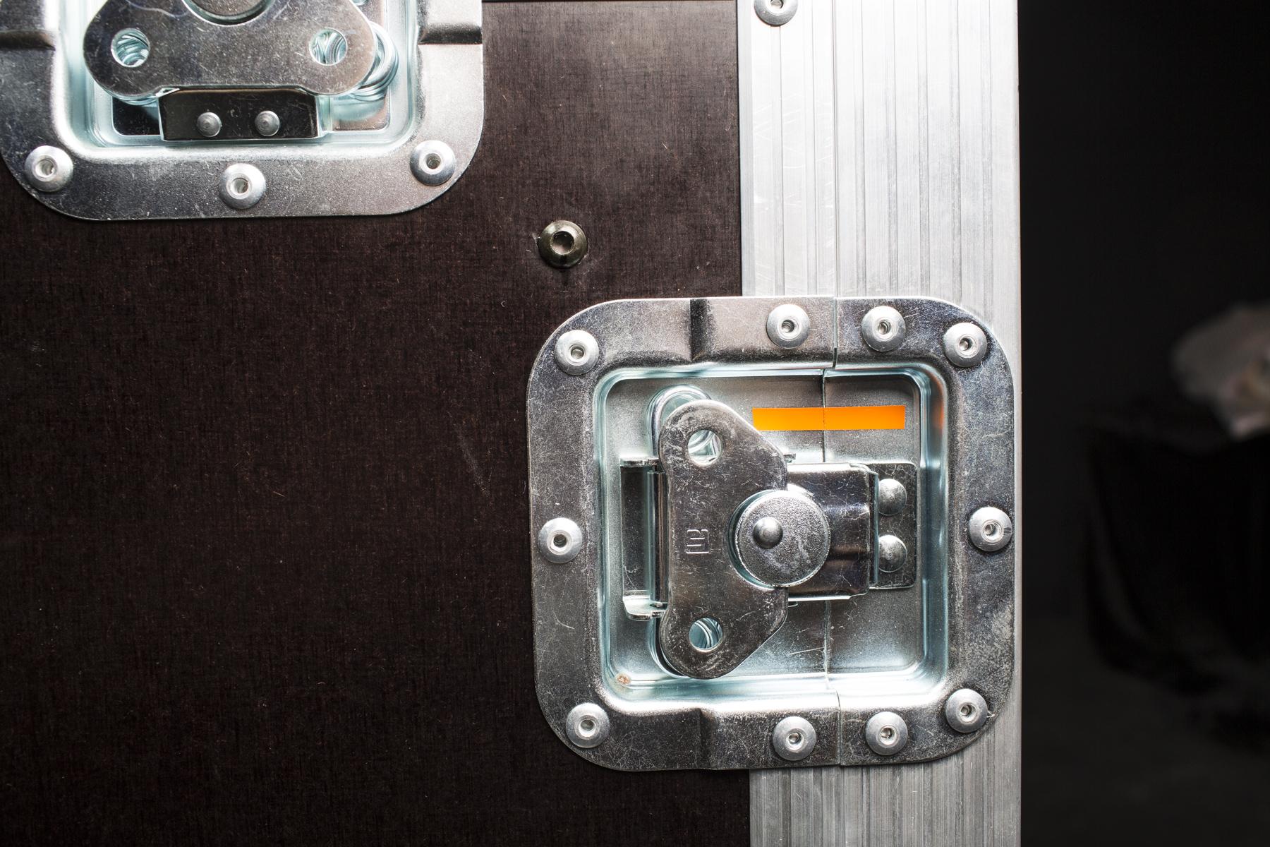
- Keep in mind, it is important to assemble the sides in accordance with the inner CASE layout. For this purpose, there are different color marks on the lock caps (pictured above).
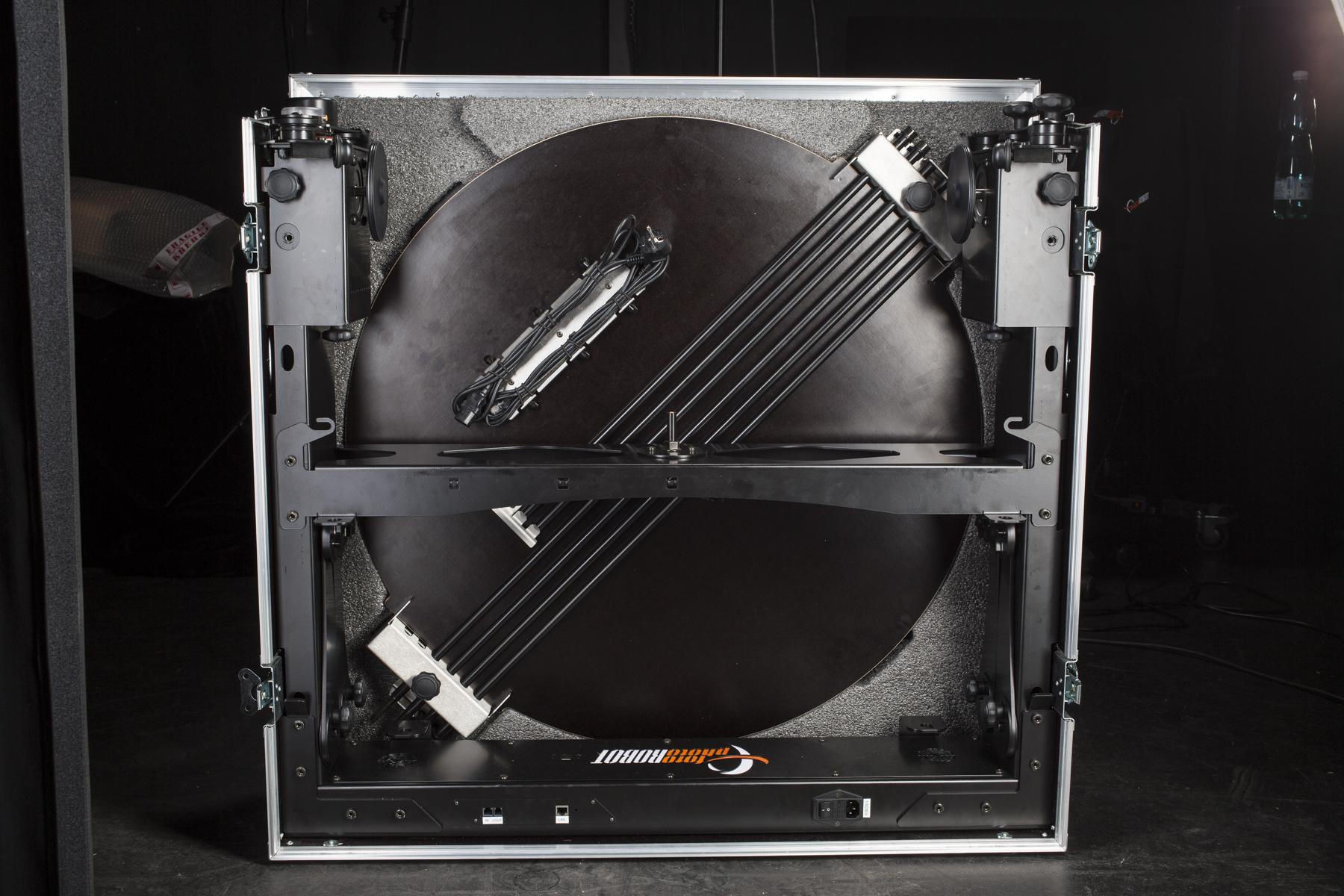
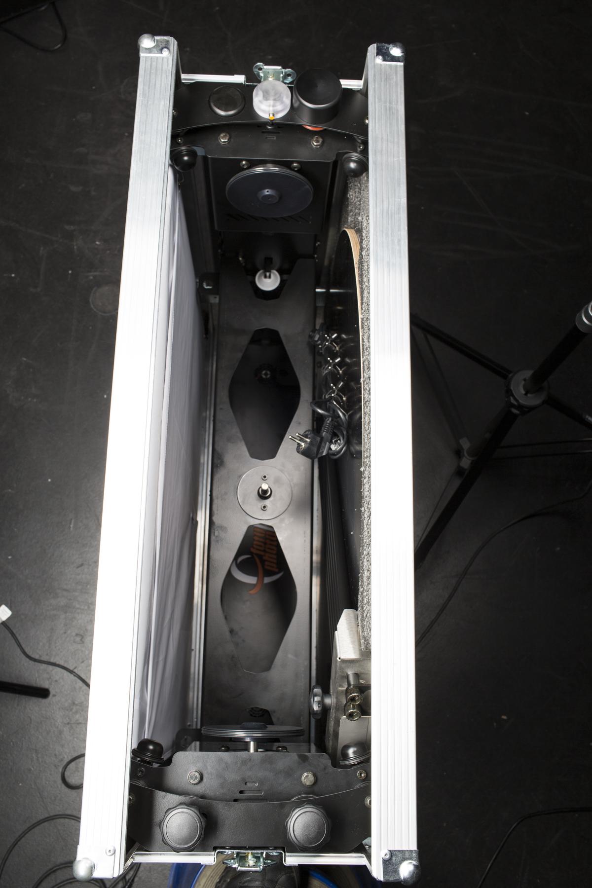
- After successful unpacking, the CASE should appear as it does in the above two images.
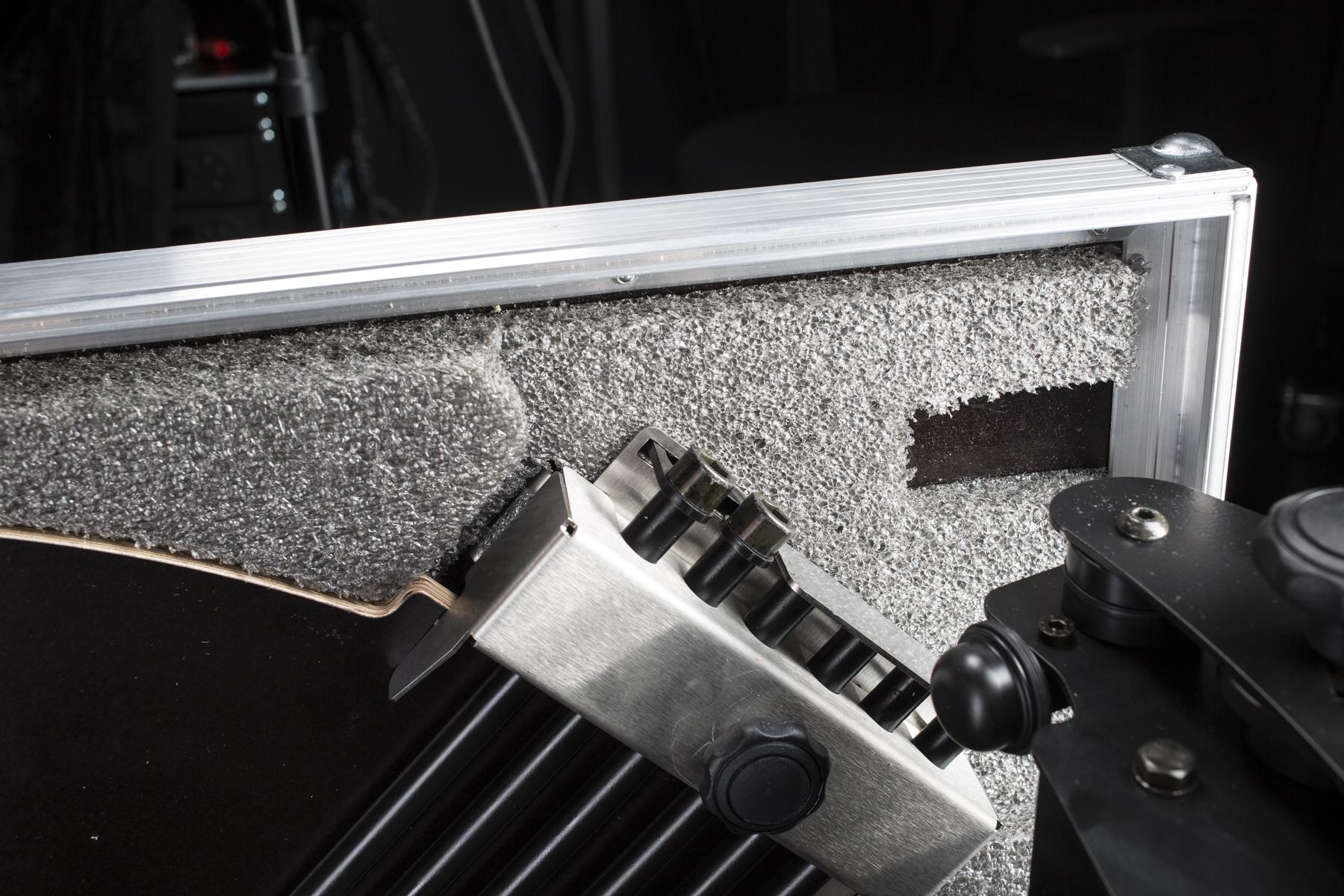
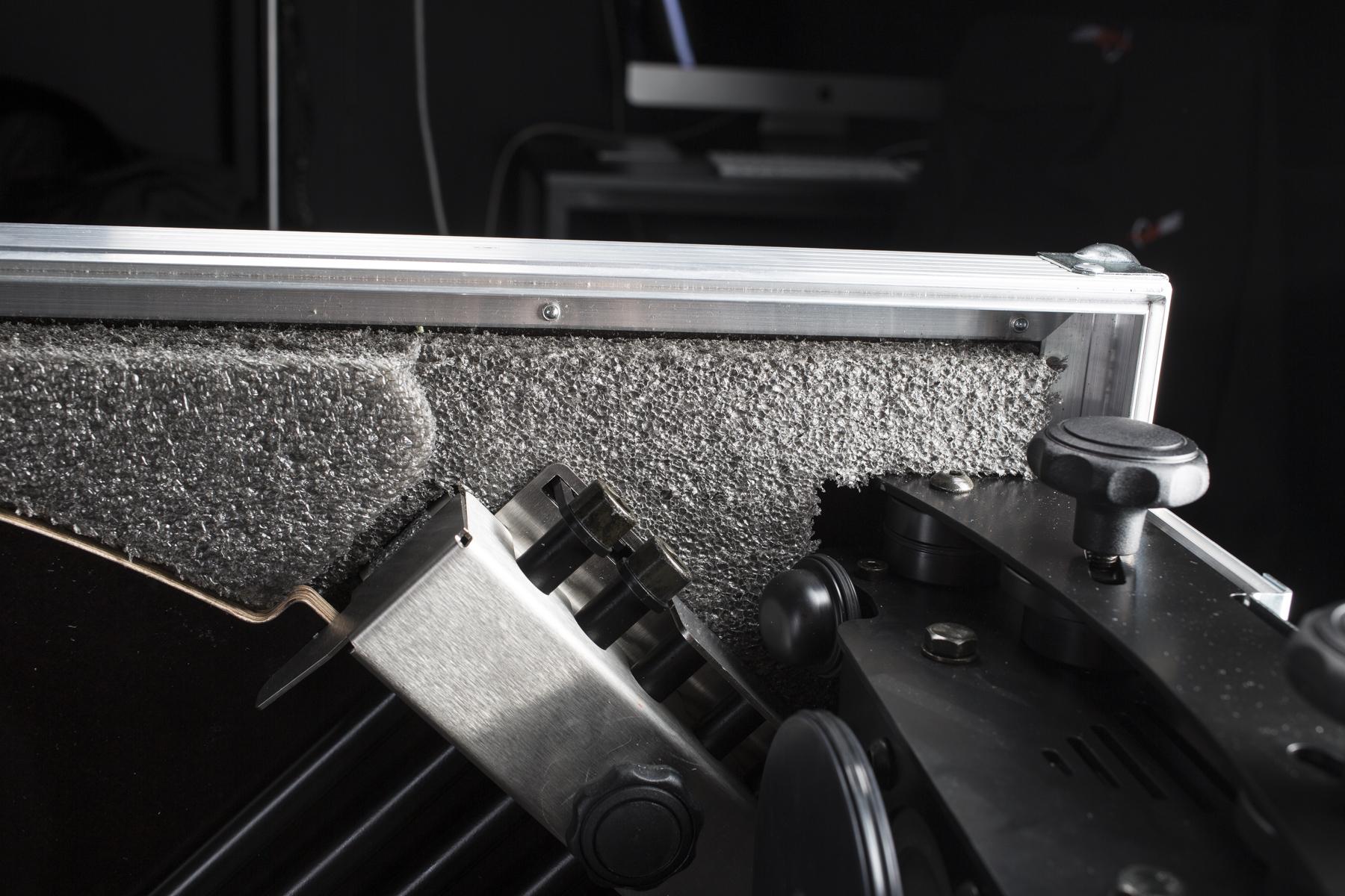
- There is a cut-out area on one side of the case to fit in the glass mount construction.
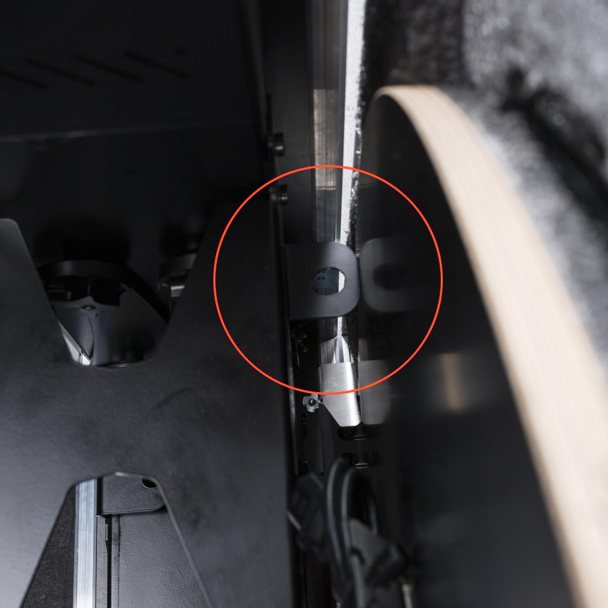
- Avoid mismatching of the sides to ensure they fit the inner layout.
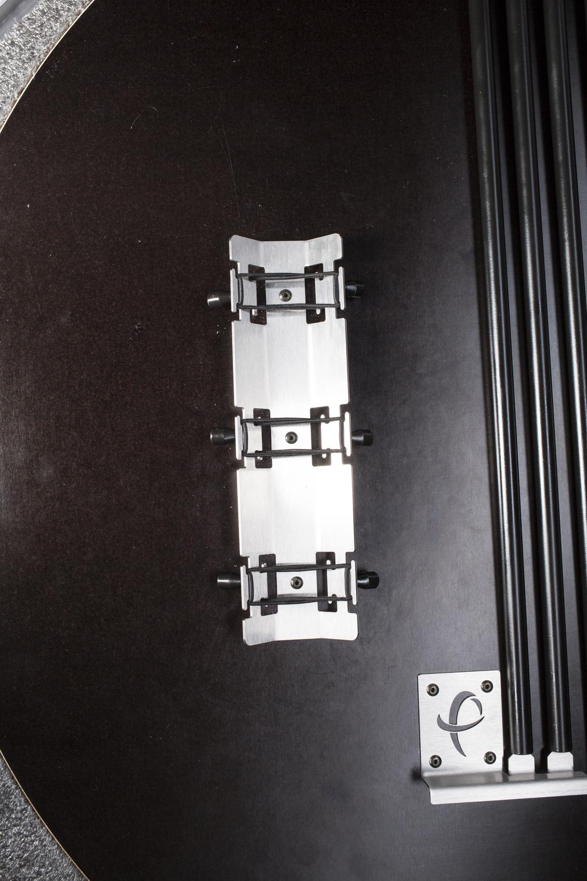
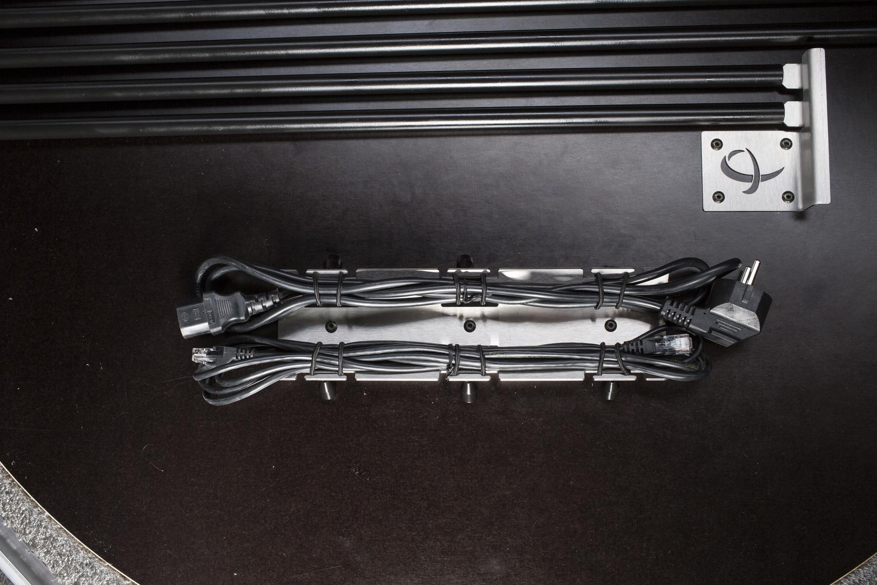
- The cables are held in position by rubber bands.
1.2.1. Fold the background to the case’s side

- There is a sophisticated method of folding the background into the case’s side to avoid creases.
- The step-by-step instructions are below.
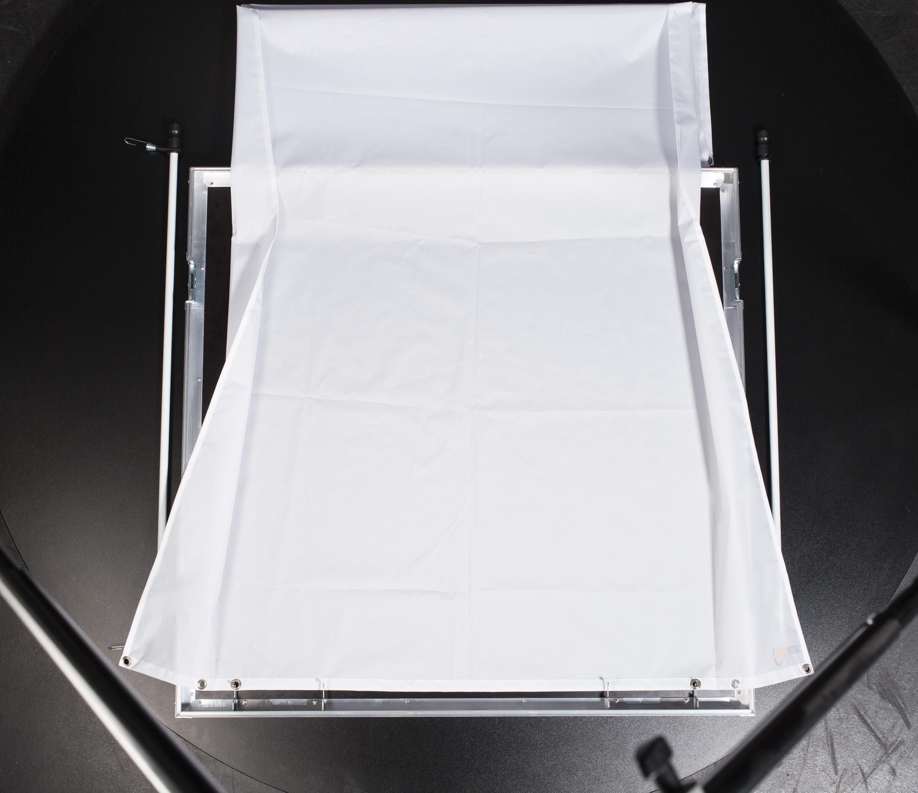
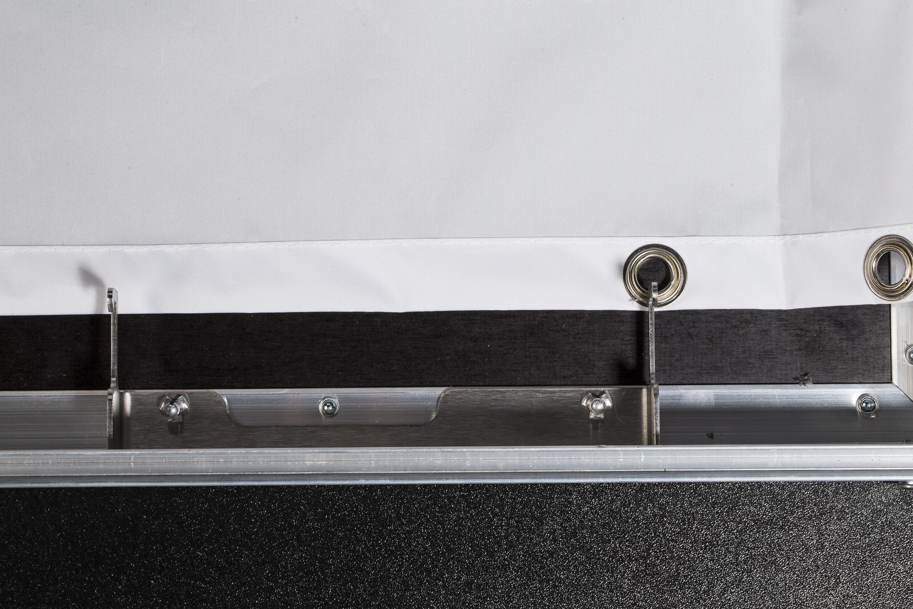
- Take the wider part of the bevelled background and anchor the third hole onto both the right and left side using the outer hooks. The edge of the background goes under the inner hooks.
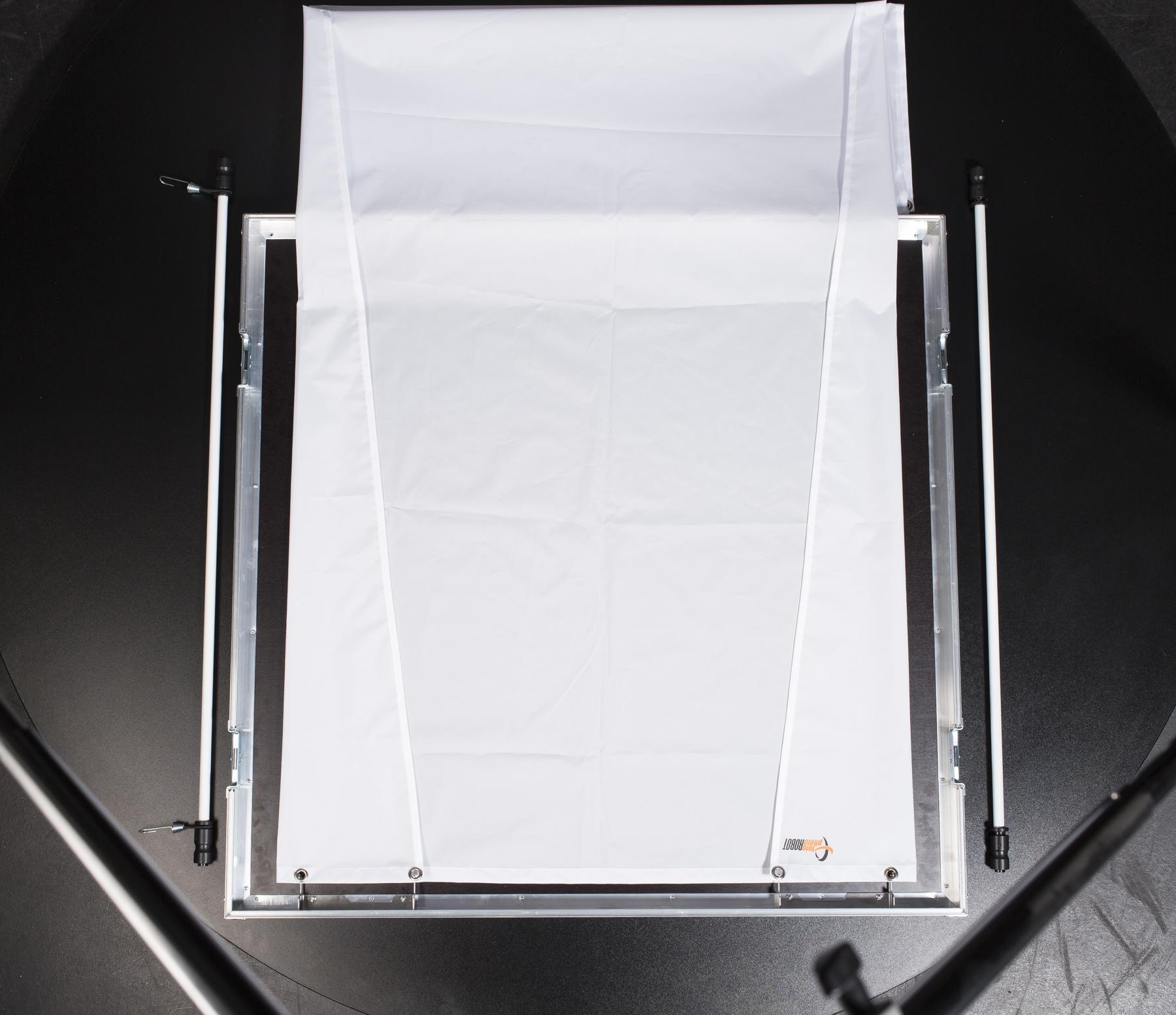
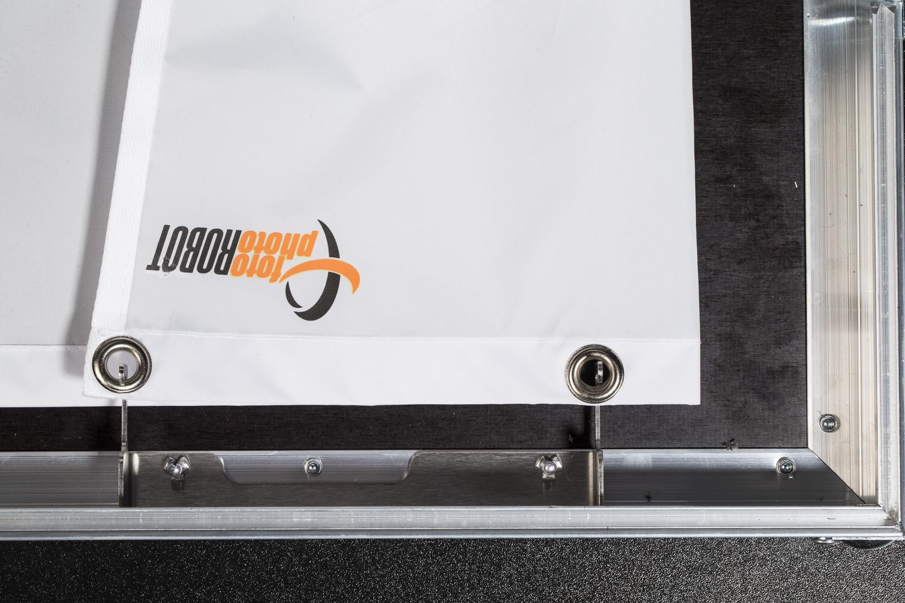
- Fold the background's corners, and then anchor the holes onto the hooks.
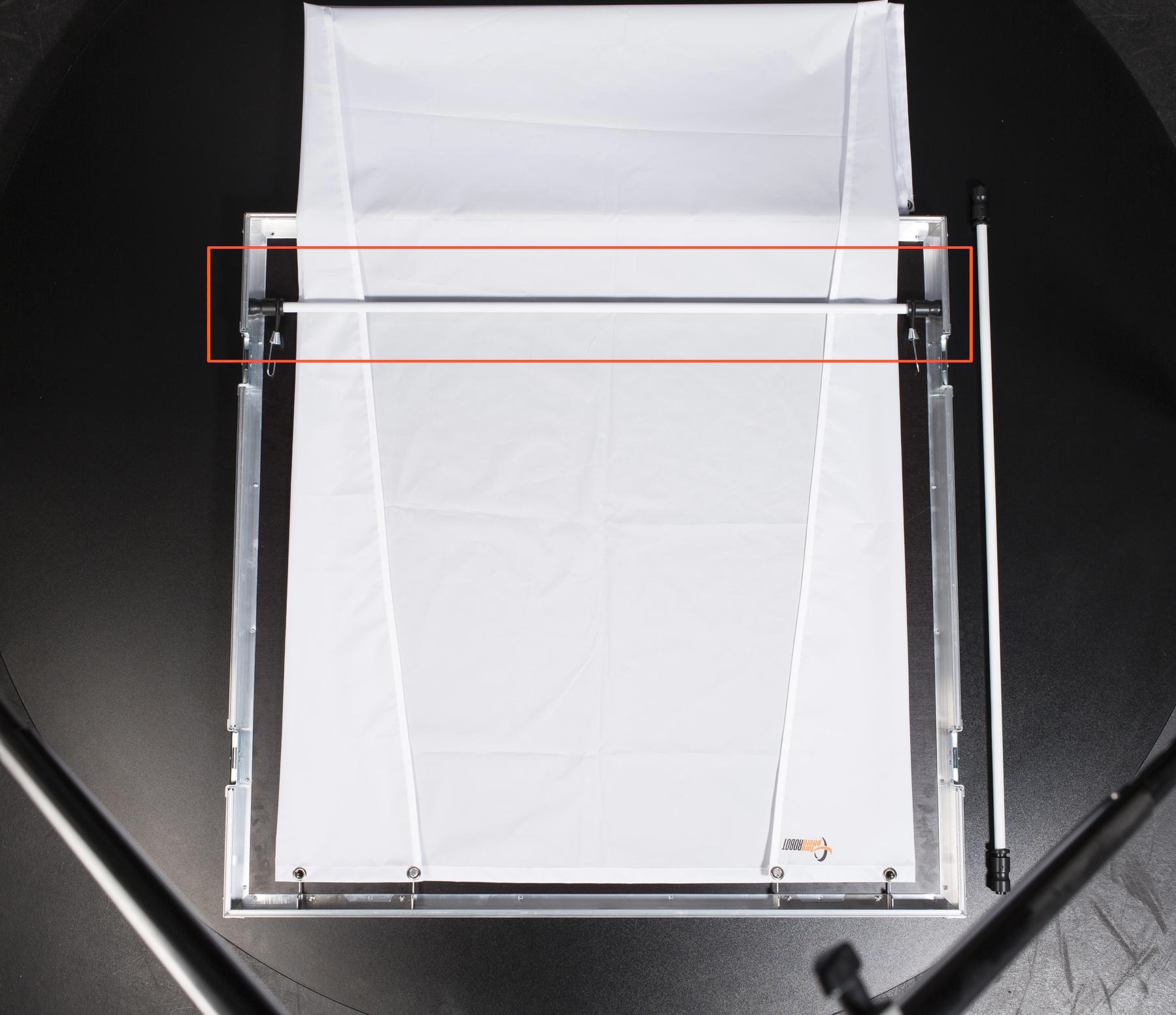
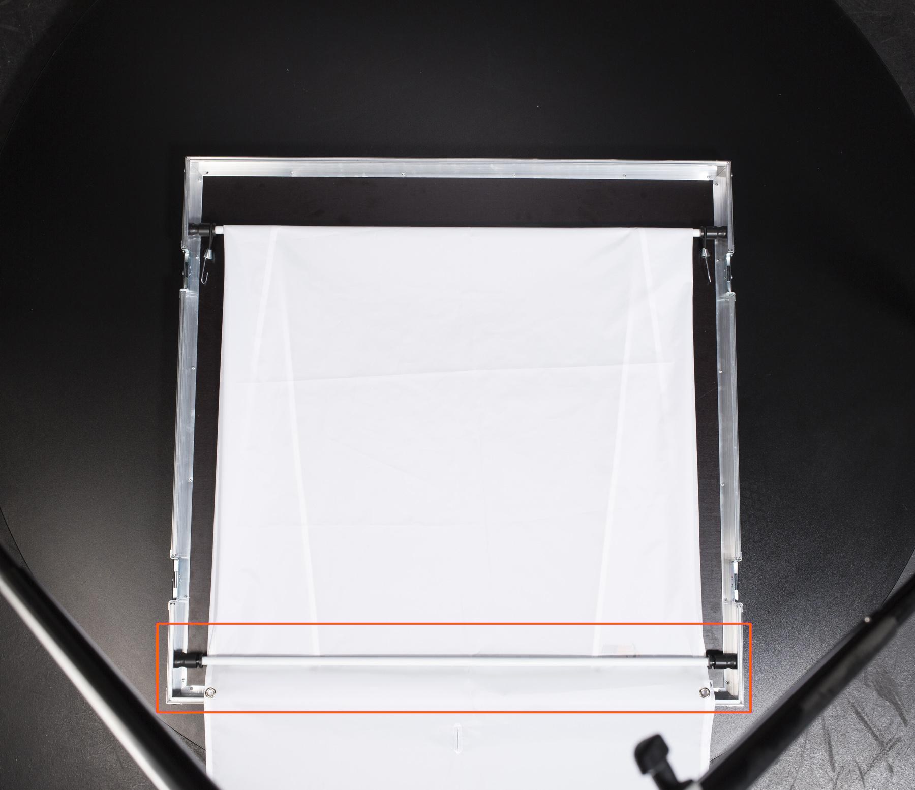
- On the other side, fasten the pole over the background.
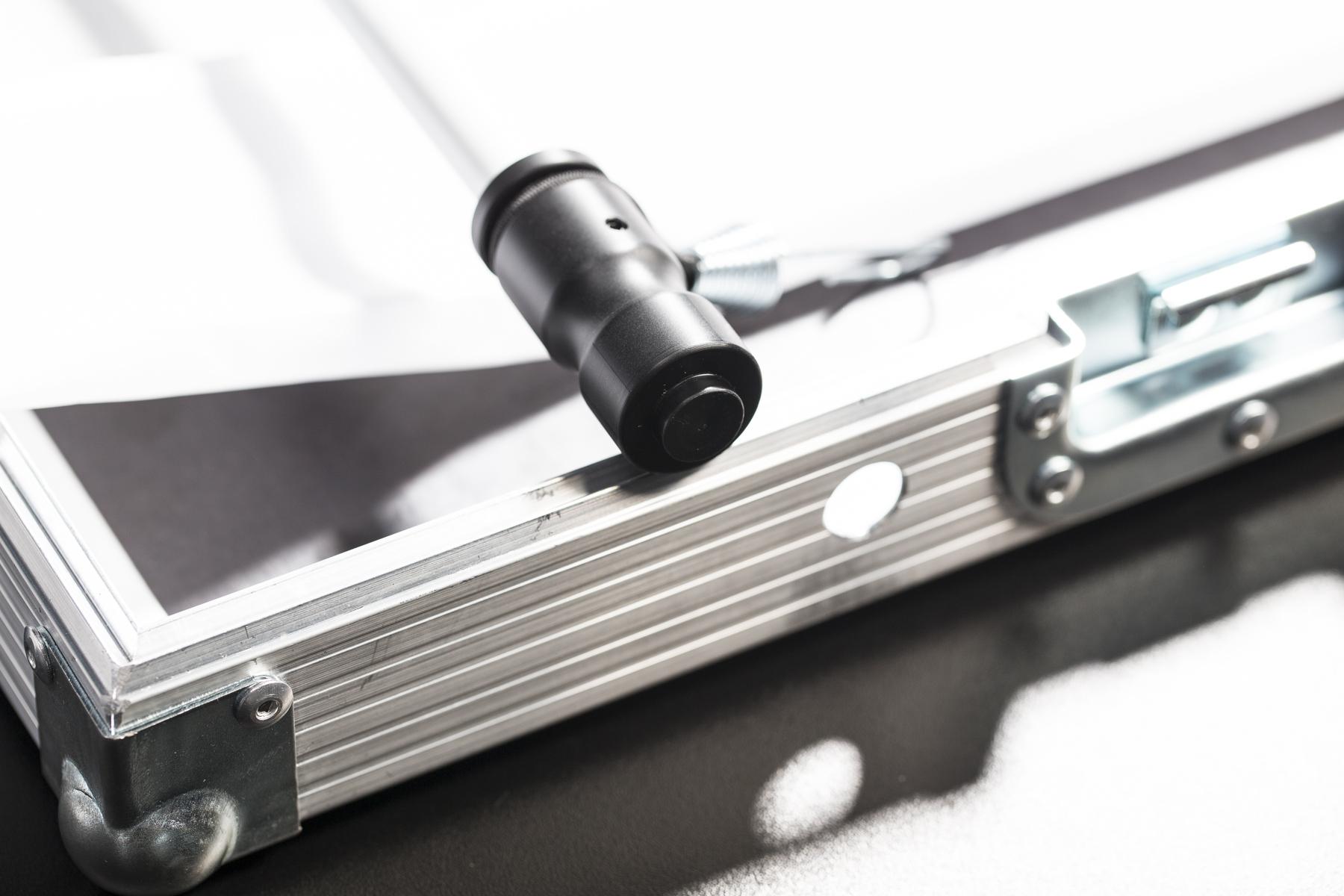
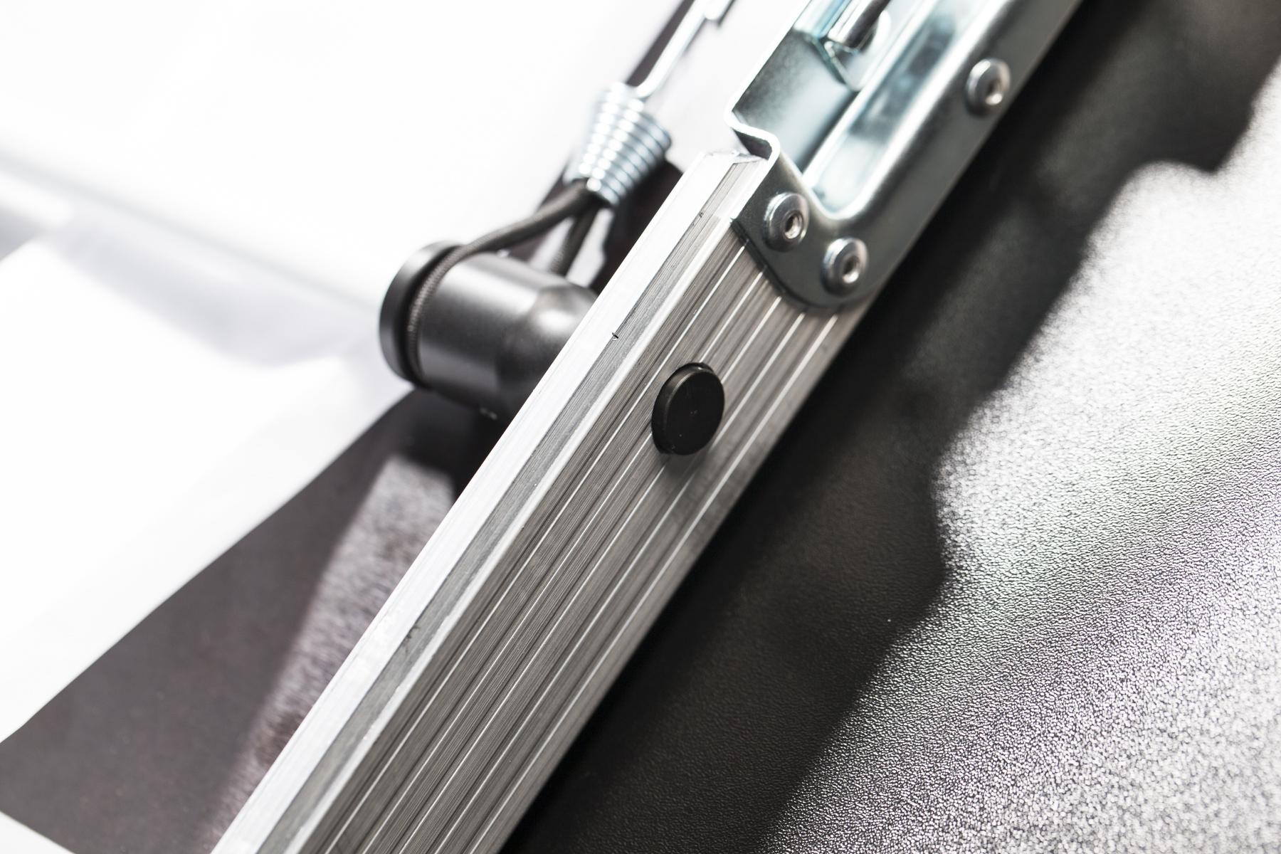
- To fasten the pole, compress its spring mechanism and fix the tip of the pole into the anchor hole.
- Fold the background over the first pole, and then fasten the second one onto the other side.
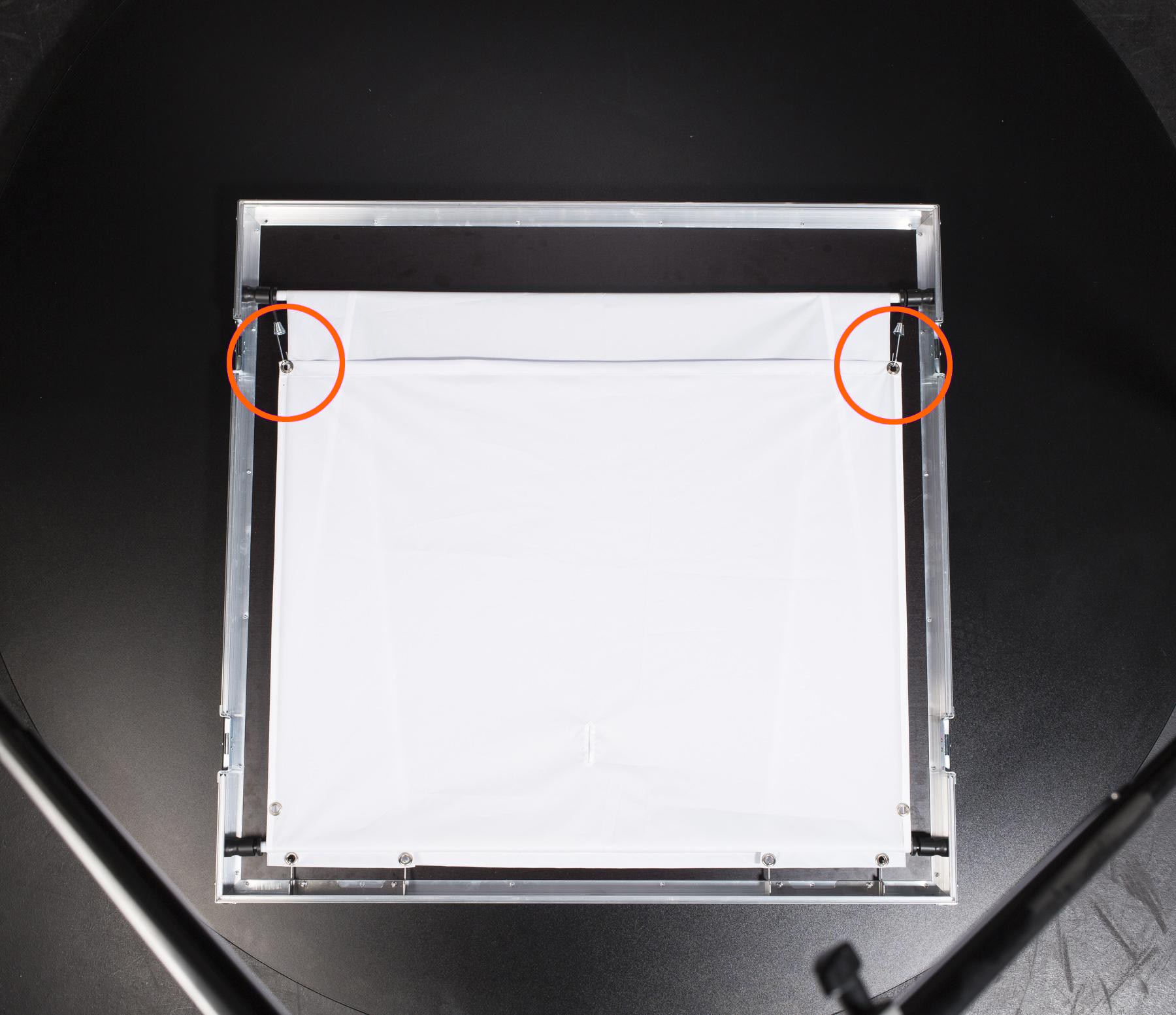
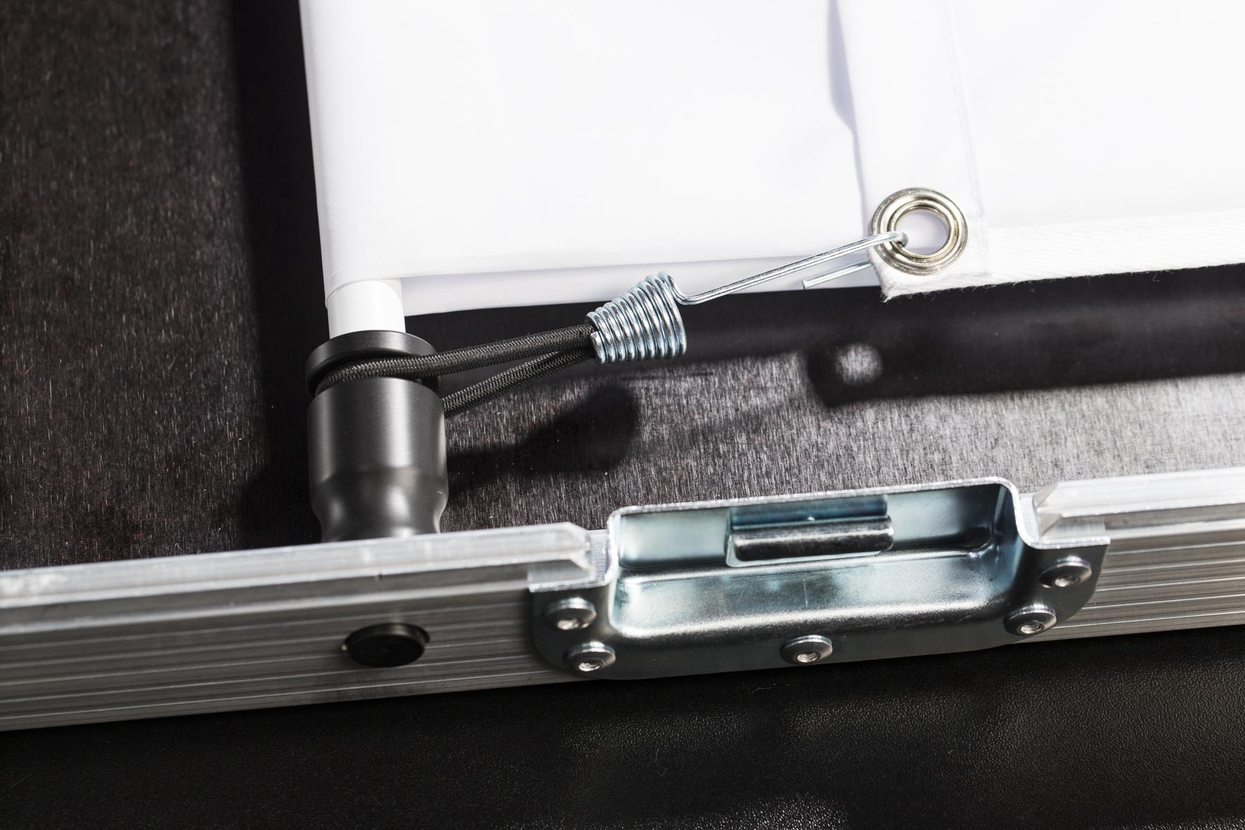
- Secure the background's corner holes by the hooks on the rubber bands attached to the pole.
1.2.2. Attach the glass plate and background poles to the case’s side

- Make sure the side is clean and free of any obstructions to avoid any damage to the glass plate.
- Place the glass plate into the hollow area of the side.
- Cover the glass plate by the wooden protection disc with the chamfered edges facing the background holders.
- Undo the rubber bands on the cable holder.
- Place the cables onto the holder.
- Fasten the cables with the rubber bands.
- Attach the background holders to the side.
- Fasten the background holders using the clamps.
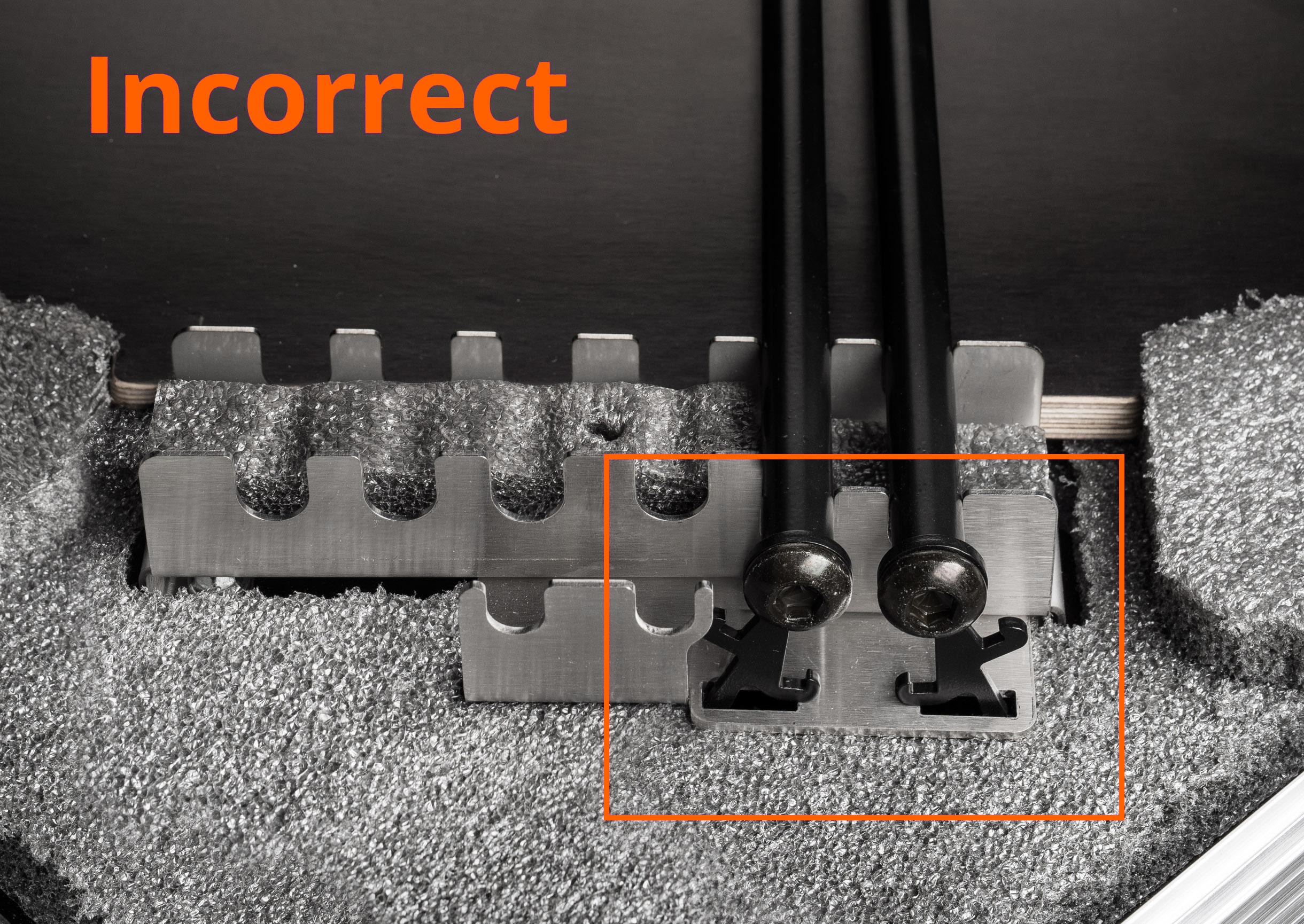
- Be aware that when the upper hooks are facing the opposite way, the background bars are not placed correctly and are at risk of shifting during transportation.
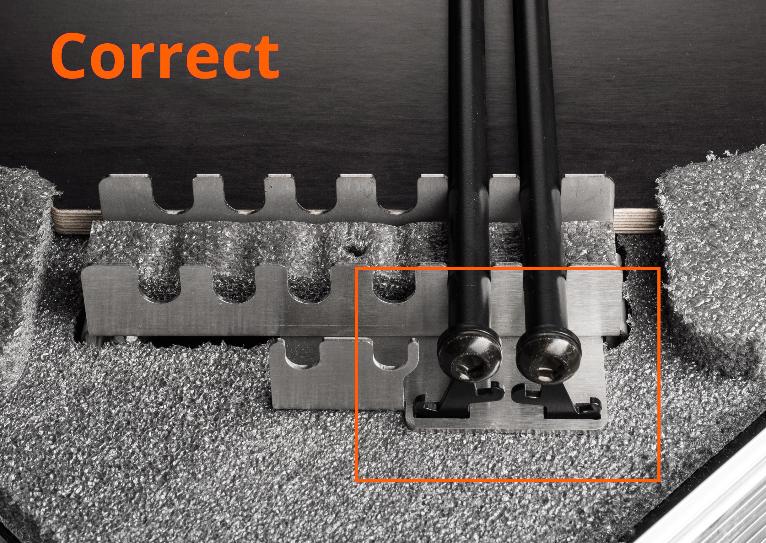
- The background bars are placed correctly when the upper hooks are facing each other.

- To join the machine base, sides and top, fasten all the lock caps.
1.3. Transportation
The outer case of the PhotoRobot CASE is made of very sturdy materials to make the robot easy and safe to transport. Nevertheless, you should avoid any bumps, collisions or jolts which could harm the electronics.
Although the CASE weighs only 62 kilograms (137 pounds), it is not recommended to carry it on your own; we suggest asking an assistant for help.
We recommend using the original cardboard box for shipping. To do so, simply reverse the steps in chapter 1.1 - Unpacking.

- Durable tilting handles are useful for easy carrying of the CASE.
2. Package Contents
The PhotoRobot CASE is designed to be used in different ways in a wide variety of photography scenarios and environments. Therefore, along with the robot, we supply optional accessories to comply with all the specific needs photographers might have.
2.1. The Case 850 Robot
The CASE contains the fundamental gear necessary to operate the robot, and to photograph either still or spin images.
What's included with the Case 850 Robot?
- 850 mm glass plate (33,5 inches)
- Control unit
- Transparent background with holders
- Cross laser for precise product positioning
- Power and data cables
- Foldable legs
- Encoder & calibration probe
- Spare X-rings
- General purpose lugs to hold lights, light dividers, diffusion panels, etc.
- Handles for comfortable transportation
NOTE: The CASE does not contain any camera nor flash lights.
2.2. Optional Accessories
With the help of our optional accessories — supplied separately, at extra cost — you can streamline your workflow to meet your needs. Please see more details below.
2.2.1. Wi-Fi Module
We supply a USB Wi-Fi module to let you connect the CASE to an existing wireless network or to establish your own Wi-Fi network independently of any other network connectivity. To work with the PhotoRobot CASE, we sell and recommend the extensively tested TP-LINK TL-WN721N (see its technical specifications). The Wi-Fi module is kept in stock and is the right choice for on-location work where a LAN connection is not available. Whenever a wired connection is possible, we recommend using LAN instead — it is more reliable and free of wireless interference.
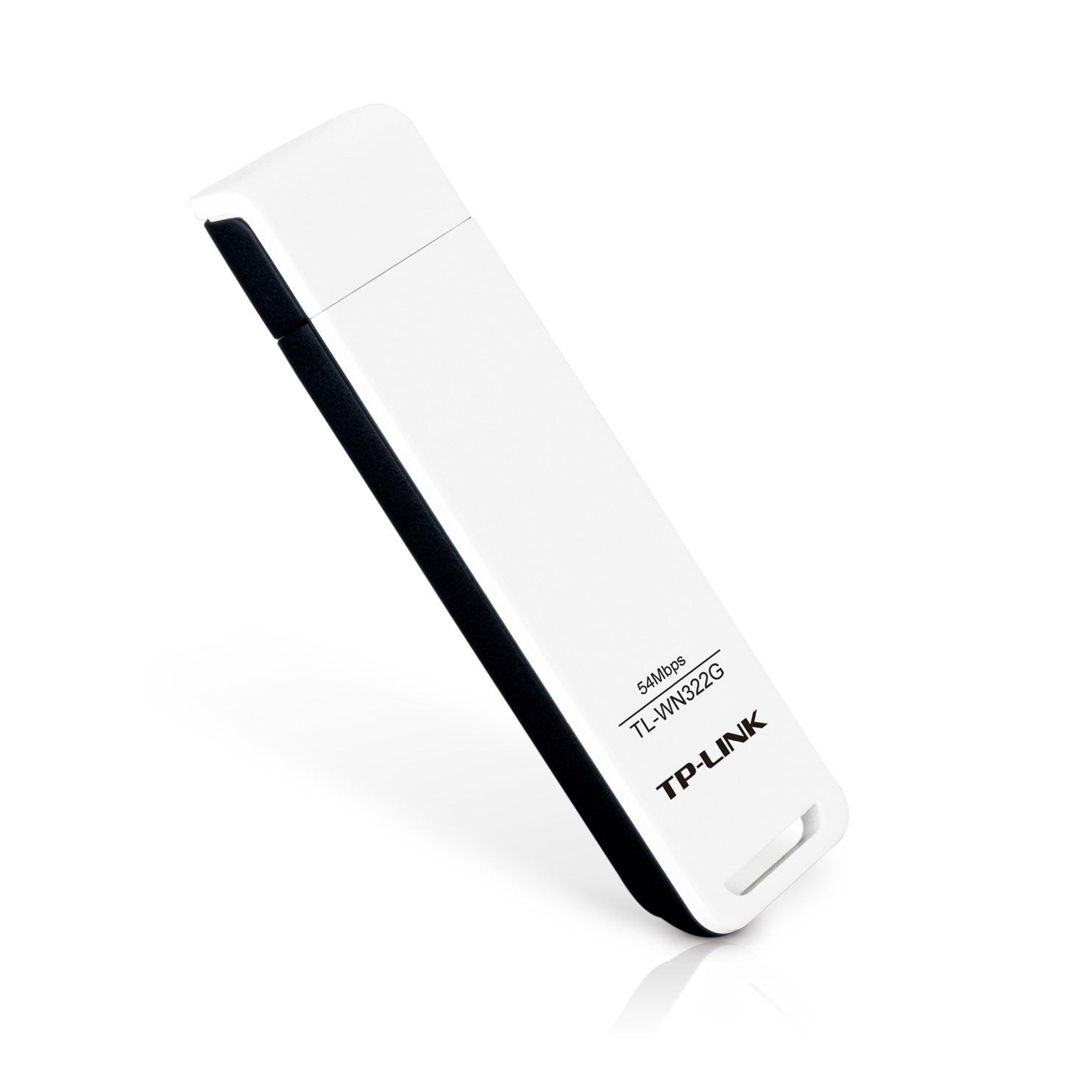
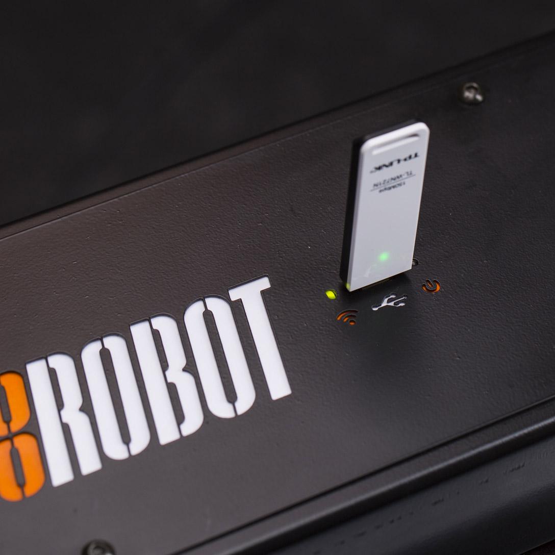
- The Wi-Fi Module uses USB to connect to the CASE.
2.2.2. Wireless Trigger
Synchronization of the camera shutter and the sequence stops can be controlled by a wireless trigger plugged into the CASE. We successfully tested the hähnel Combi TF Remote Control with Canon cameras.
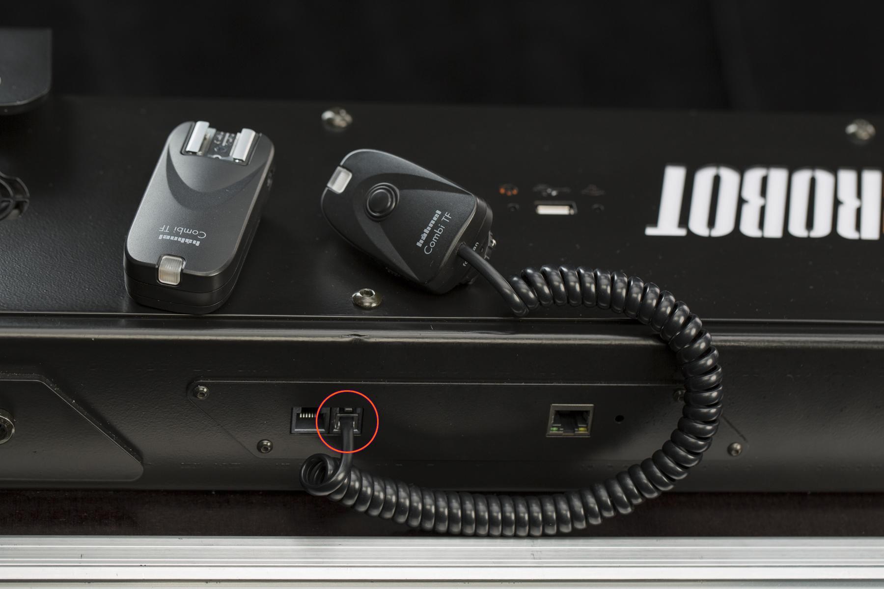
- The wireless trigger uses an integrated 4P4C (RJ9) output socket.
2.2.3. Cable Trigger
Synchronization of the camera shutter and the sequence stops can be controlled by plugging the cable trigger into the CASE.
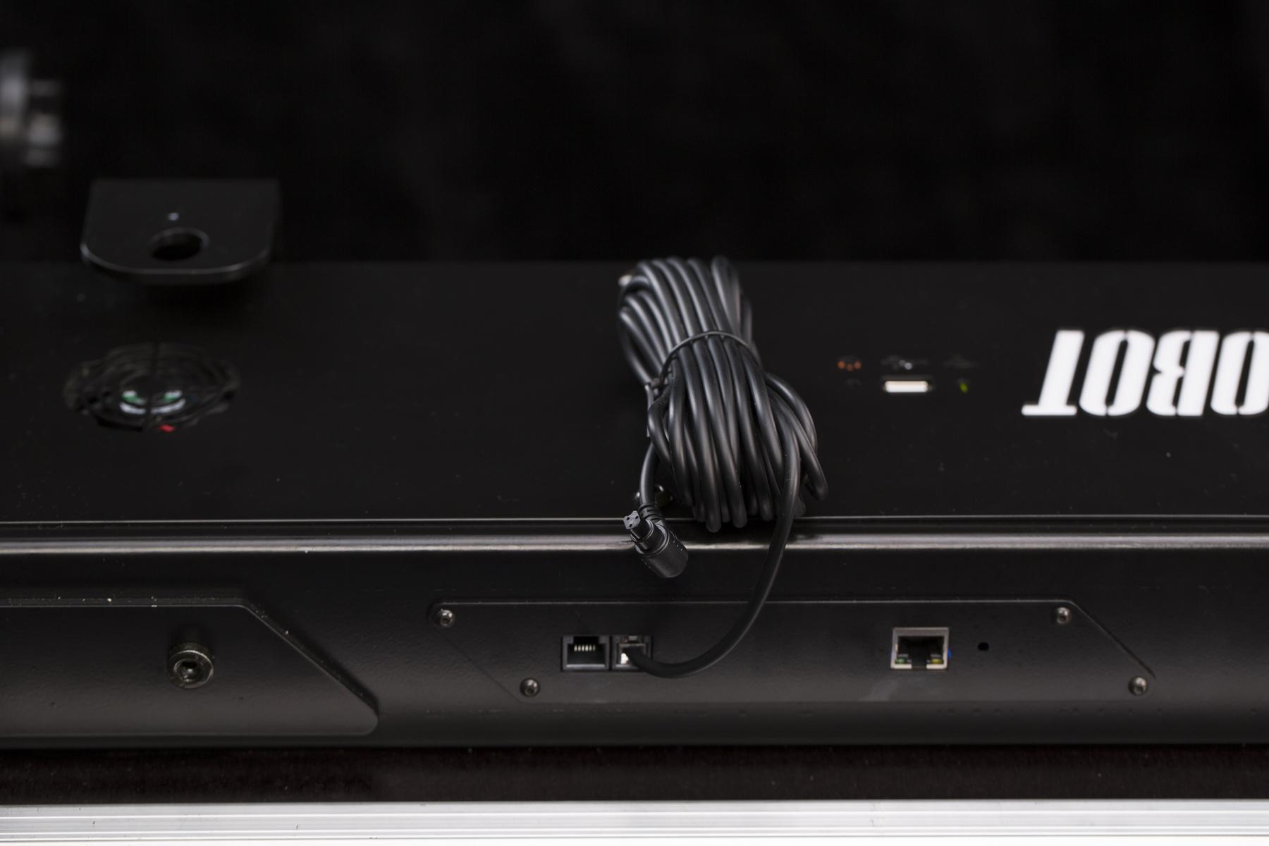
- The cable trigger uses an integrated 4P4C (RJ9) output socket.
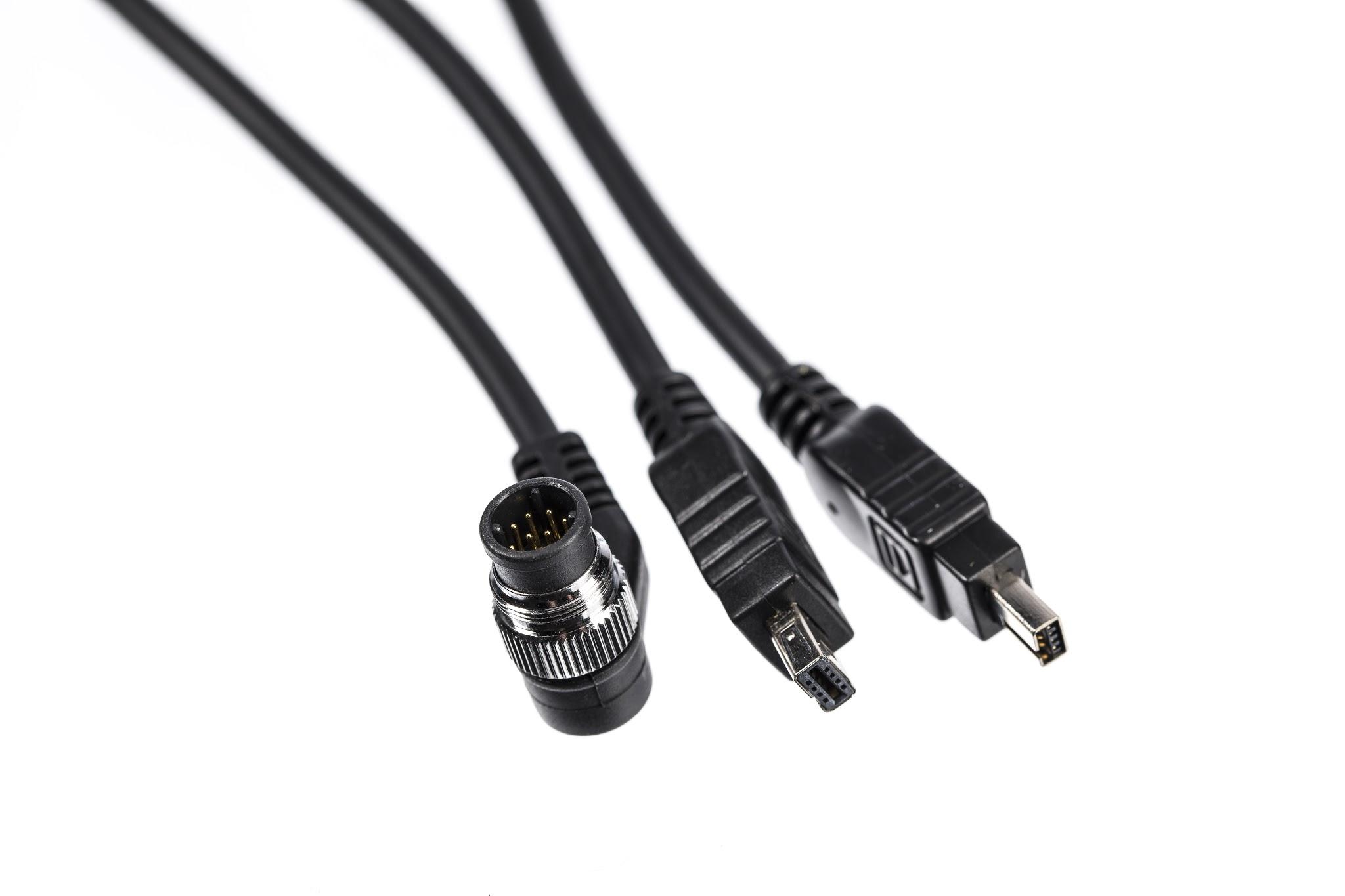
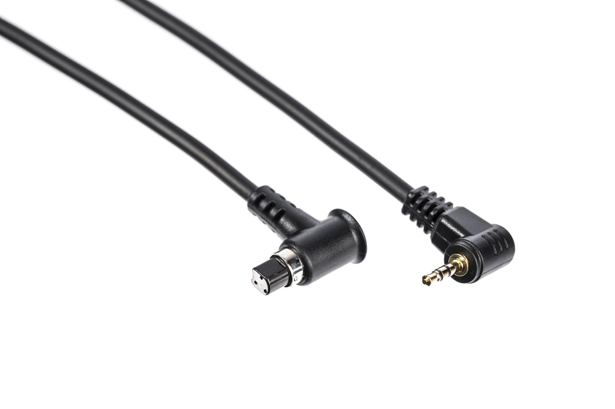
- Triggers are available for supported camera models — see the PhotoRobot compatible cameras list.
2.2.4. Foot Switch
The Foot Switch is a practical HID (Human Interface Device) manufactured by PhotoRobot to accelerate your performance. Any operational function (e.g. start sequence, run test shot, turn the plate, set zero position etc.) can be assigned to the switch so you can access functions instantly by just stepping on it. It is also possible to connect two Foot Switches to get four easy access operations. The Foot Switch is an optional accessory, supplied separately at extra cost.
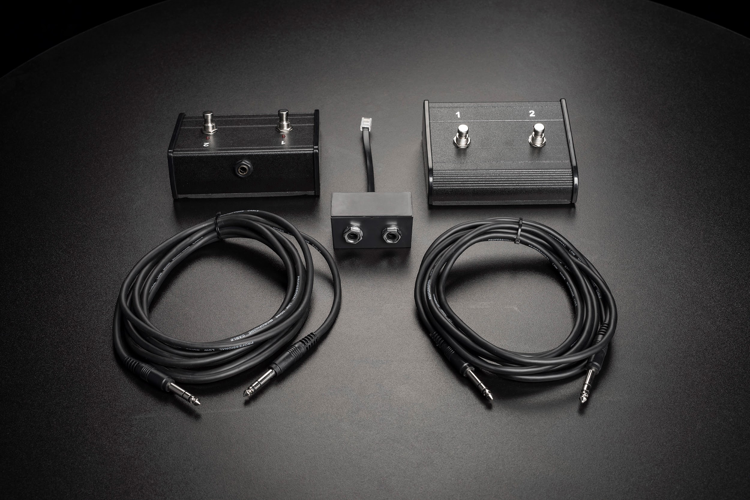
- The PhotoRobot “Foot Switch Control Set” consists of a pair of pedals, and a pair of 6.3 mm jack cables and 6P6C (RJ12) - 6.3 mm jack reduction.
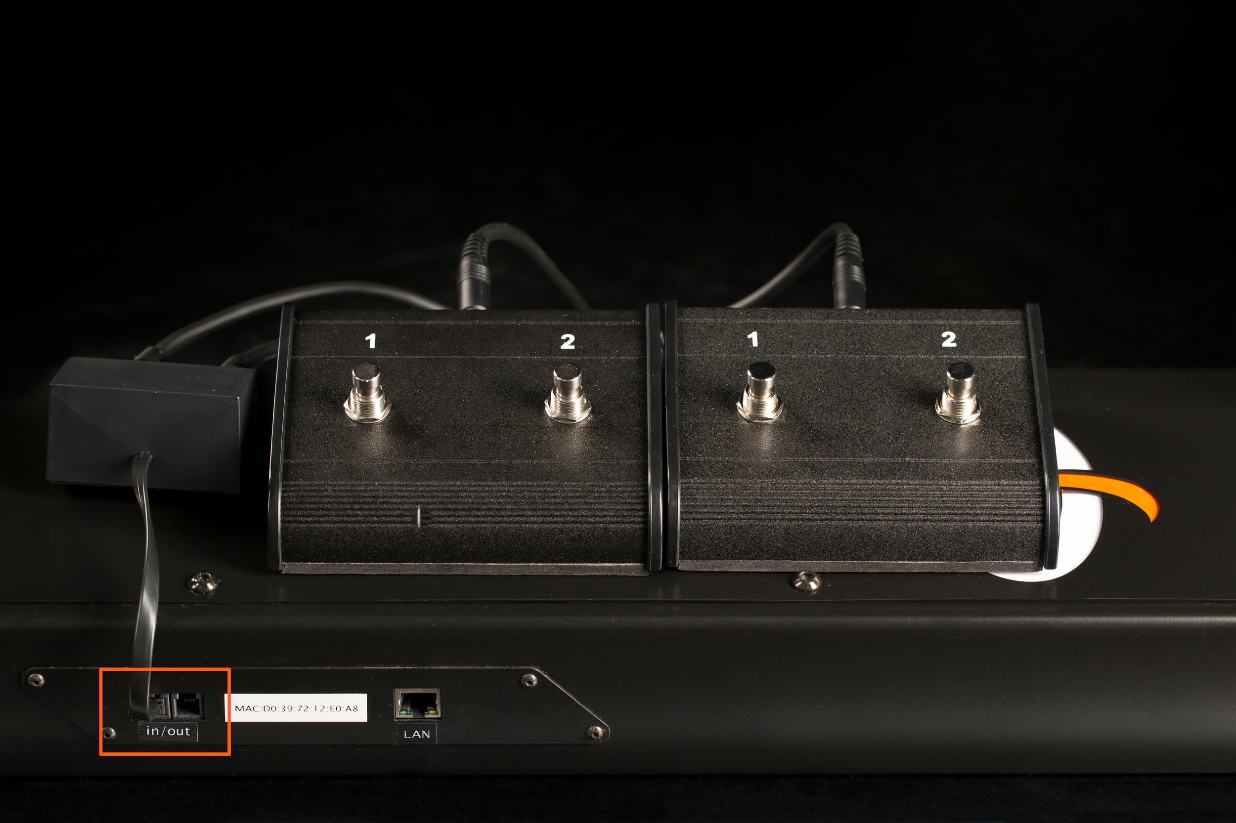
- An integrated 6P6C (RJ12) input socket is used to plug the Foot Switches into the CASE.

- The browser-based app only displays the status of designated input sockets. To assign functions to the foot switch buttons, it is necessary to use an advanced software (PhotoRobot Controls).
2.2.5. Custom Accessories
You do not need to depend only on the accessories provided by PhotoRobot. Both input and output sockets are fitted with standard registered jacks – 6P6C (RJ12) & 4P4C (RJ9). Feel free to use the Circuit Diagram to adapt any device to work with your CASE (e.g. triggers, switches, signal lights etc.). However, be aware that elementary electrical safety & maintenance knowledge is required, and it is highly recommended you ask your local electrician for help if you are not trained in this area.
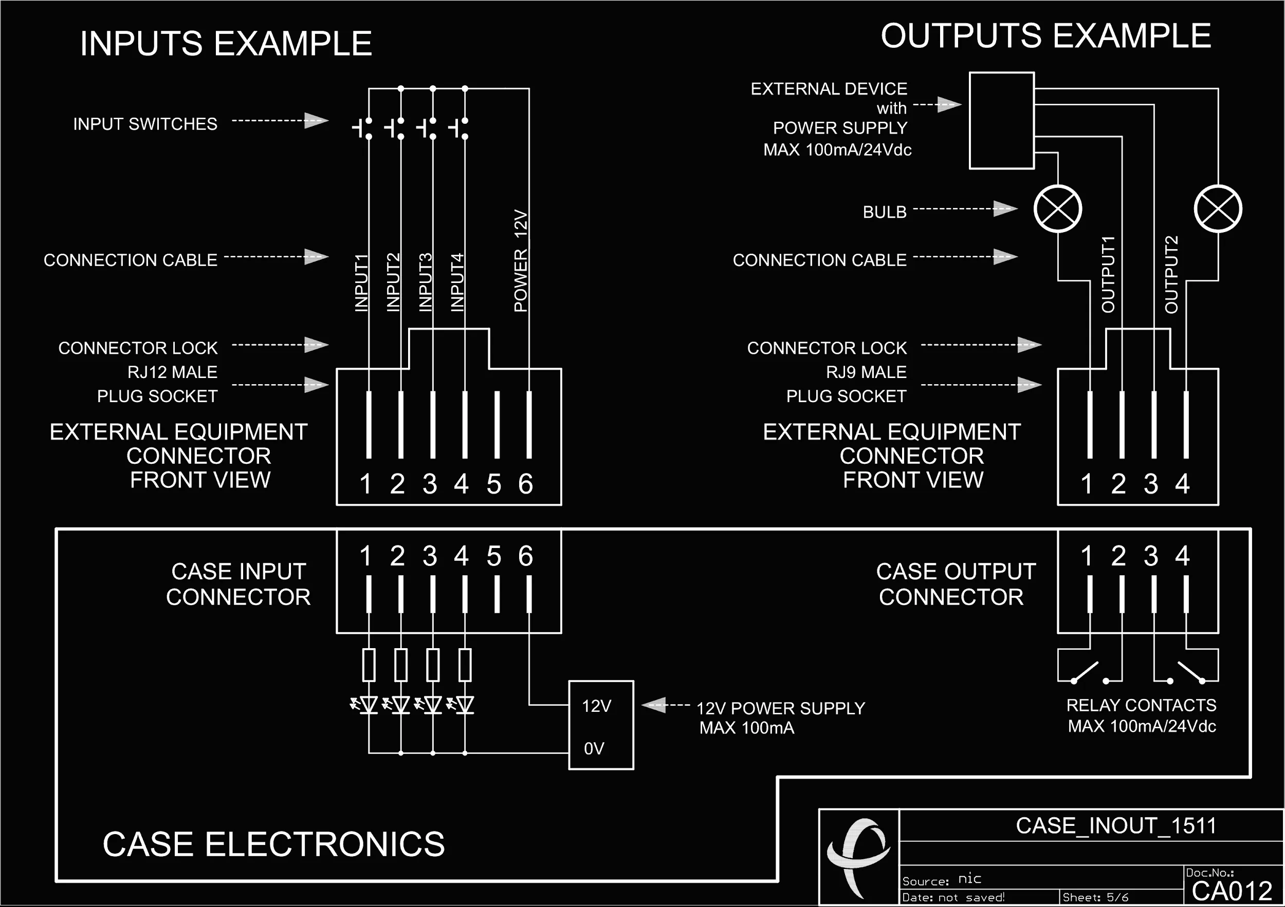
- Feel free to download the Circuit Diagram above for use with the CASE.
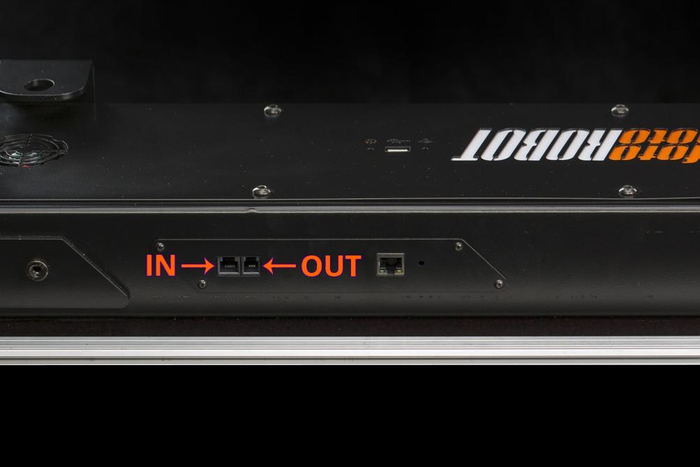
- IN and OUT registered jack sockets are located at the CASE’s base.
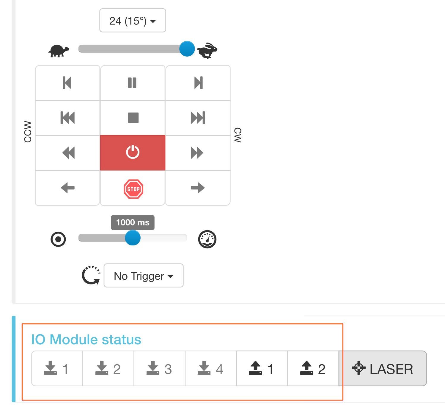
- The custom adapted device can be controlled by IN & OUT buttons at the bottom of the browser based app.
3. Assembling the CASE
Bringing the CASE from a packed to a working state is an easy and fast task if you follow four steps depicted below. Anyone capable of tying their own shoes can master it in no time.
3.1. Open the Sides
First, it is best to start by opening the case and keeping the robot parts attached to the sides until you need them for later steps.
- The CASE uses sturdy turn locks to secure the sides.

- Everything is firmly attached to the CASE’s side.
- Unscrew the background pole holders and set them aside.
- Take the background poles out.
- Undo the rubber bands holding the cables.
- Take the cables out.
- Tie the rubber bands up so they do not get lost.
- Take out the MDF protection plate.
- Take out the glass plate.
- The side is empty now.
3.2. Anchor the Base
To give the CASE maximum stability for secure operation, it is necessary to anchor the base by using the foldable legs. See the instructions with illustrations below.

- To unfold the legs, unscrew the locks and push them upwards.
- To secure the folded legs, push the locks down and screw them in.
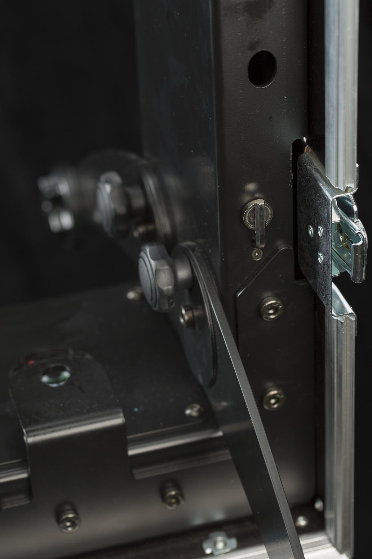
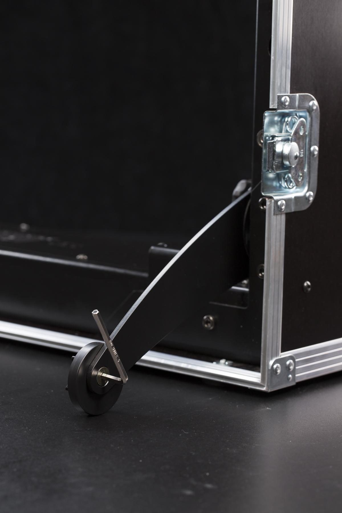
- To level the CASE properly, use the hex key fitted in the base to unlock the off-centre ring.

- Next, fine-tune the CASE’s stability by revolving the off-centre ring. When you find the best position, tighten the ring using the hex key.
3.3. Mount the Glass Plate
Mounting the glass plate is simple. The trickiest part of mounting the plate is not smudging the glass while mounting it to the base. It’s advisable to use a pair of clean gloves when handling the glass plate.
Note: The latest generation of the CASE 850 (the optical-sensor version, without the calibration suction cup) uses a glass plate with a small bevel ground into its edge. Insert the plate so that this bevel sits on the underside, above the hidden optical sensor that reads the plate position. Earlier plates without the bevel have no required orientation.
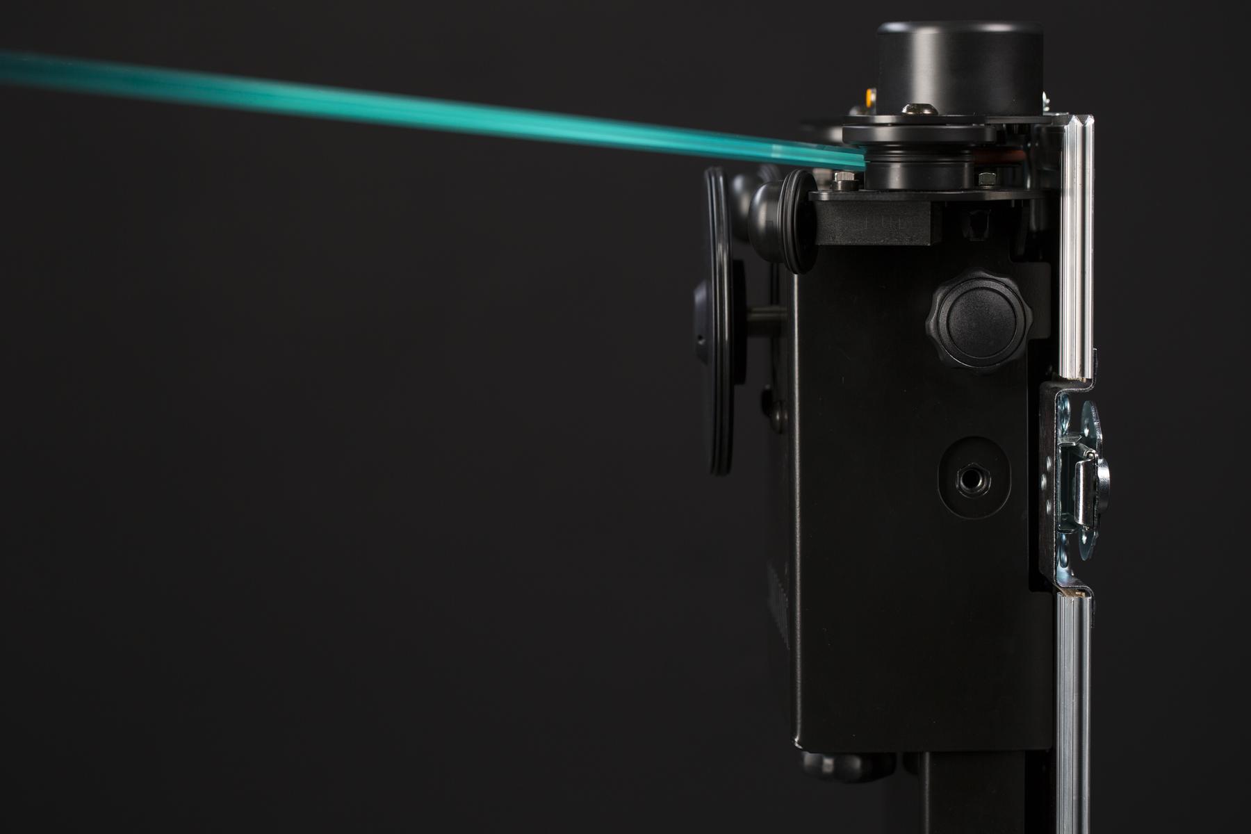
- Place the glass plate at the side where the encoder is. You need to slightly tilt it so the edge gets under the guide wheel.
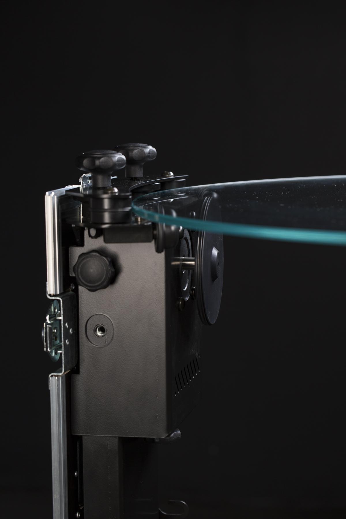
- Lay the glass plate down on the opposite side of the CASE.

- The tilted glass plate is under the guide wheel at the opposite side of the CASE.
- The glass plate lays down.
- The glass plate is locked in position by a set of moveable guide wheels.

- The moveable guide wheels securely lock the glass plate in position.
3.4 Mount the Background
If you wish to shoot on a pure white background, we supply one for your convenience as an integral part of the CASE. The material and shape makes it easy to achieve a pure white background without the need for post-production. Be sure to handle the background with care, taking precautions to prevent wrinkling or discoloration. Though it is possible to clean and iron the background, it may alter its quality and lifespan.
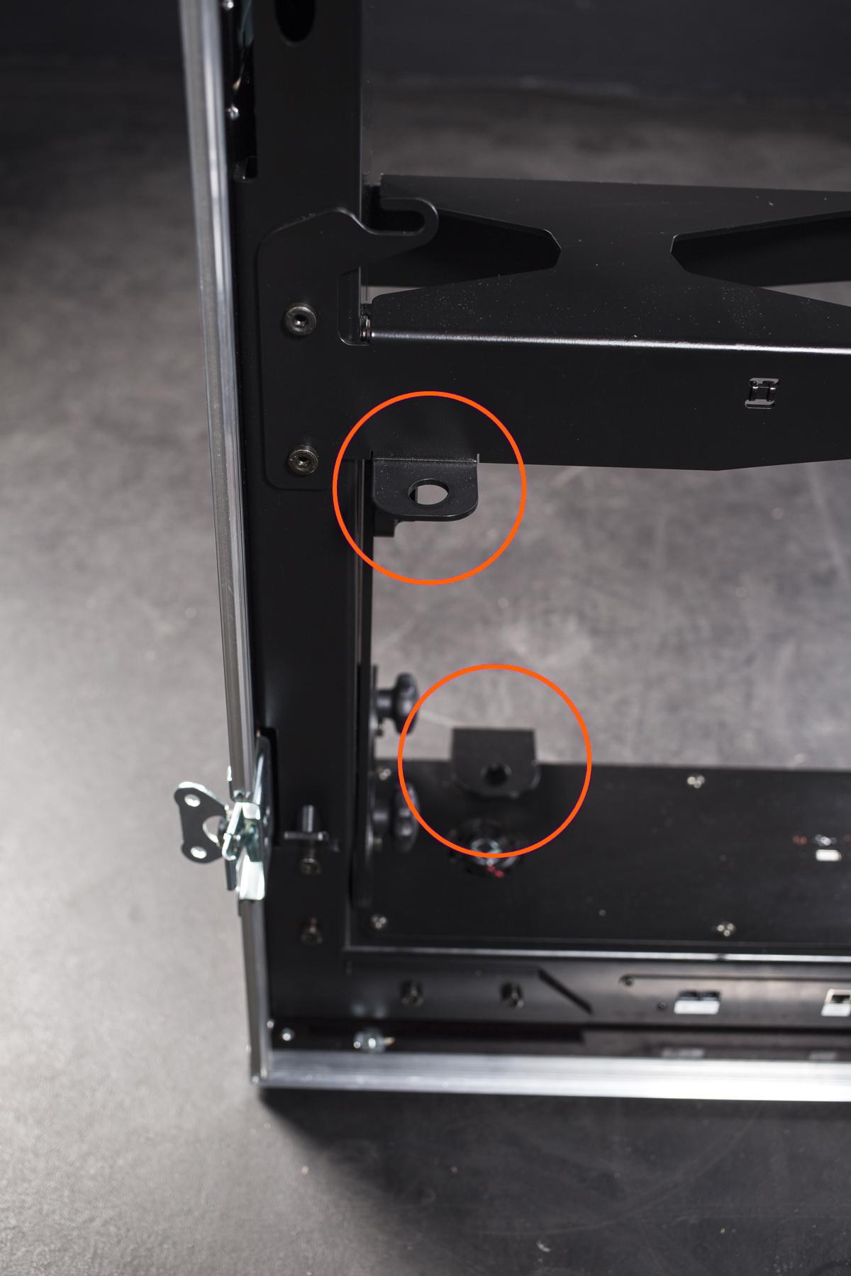
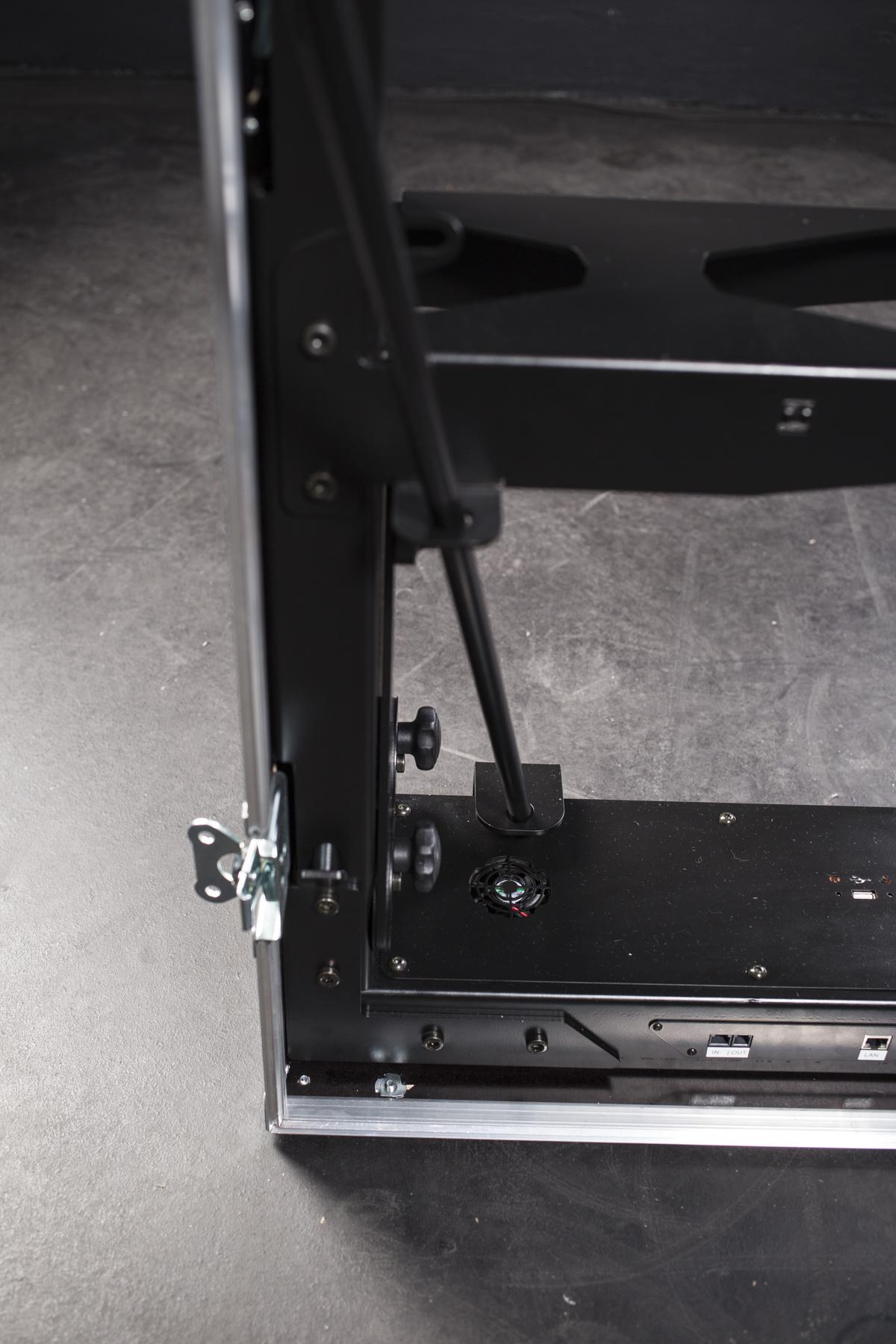
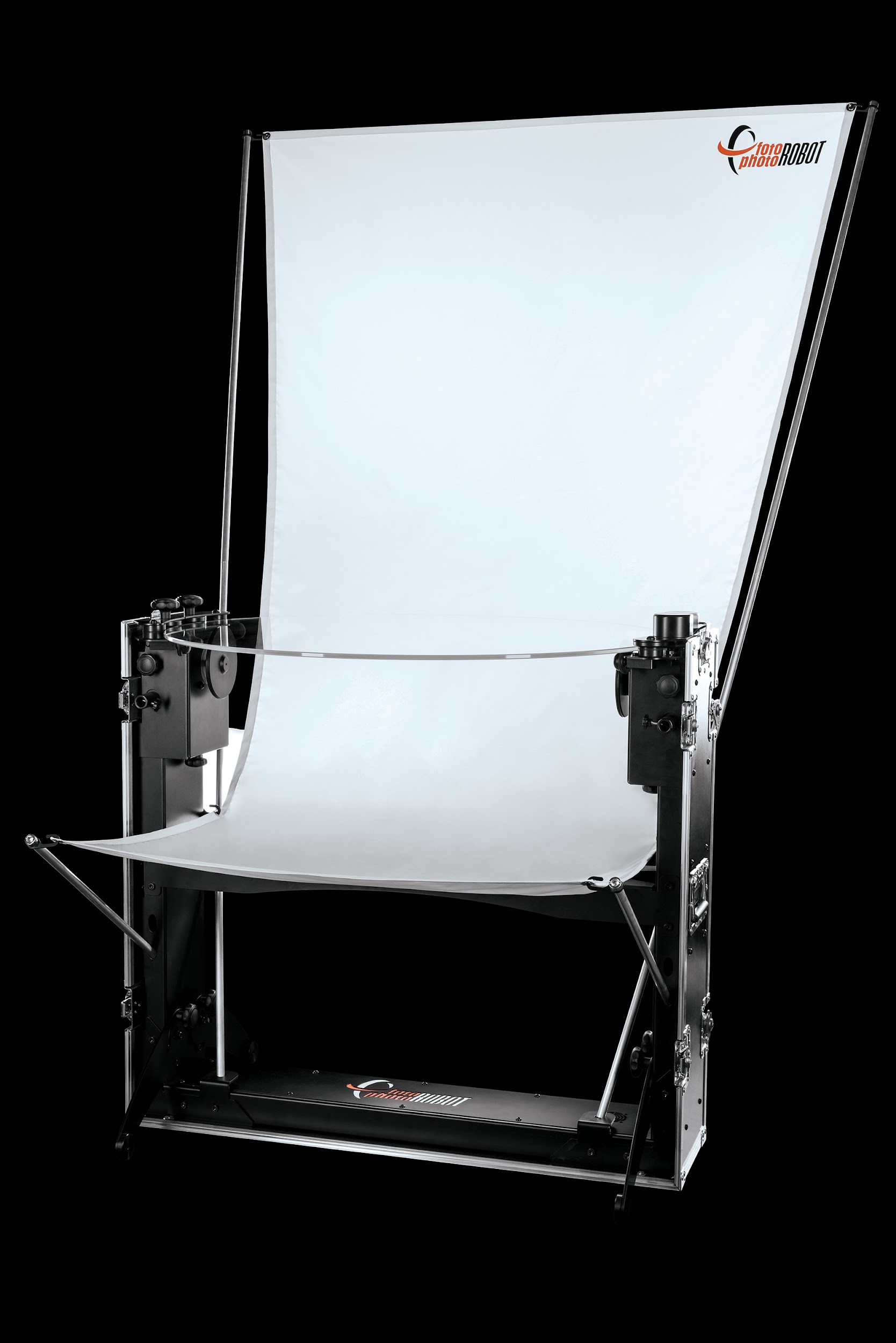
- Insert the longer poles through two eyelets on both sides of the CASE. Use the poles without the hook.
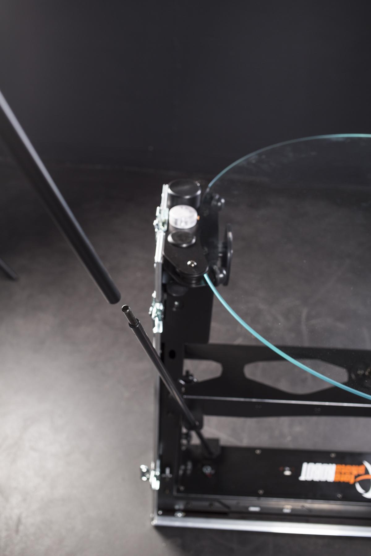
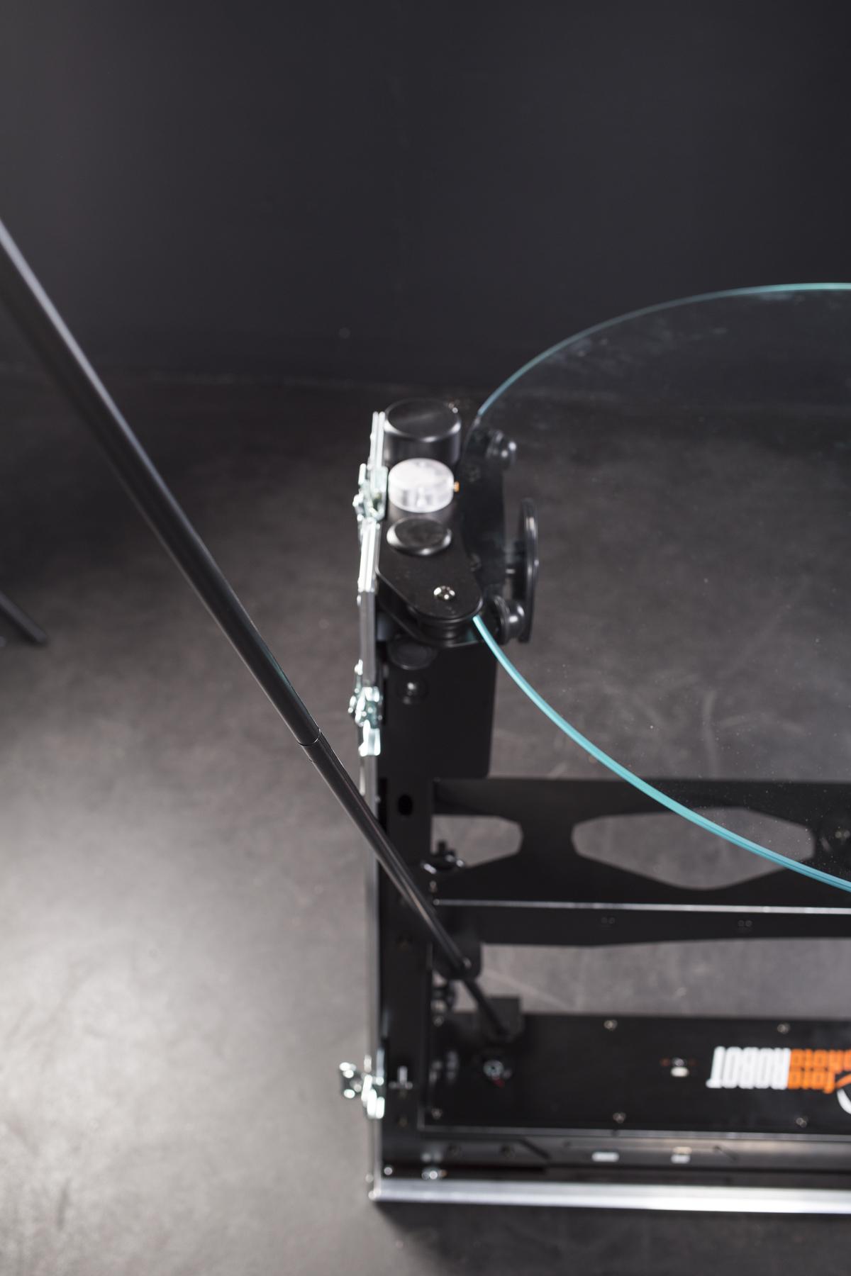
- Attach the longer poles with the hook to the poles already mounted on the CASE.
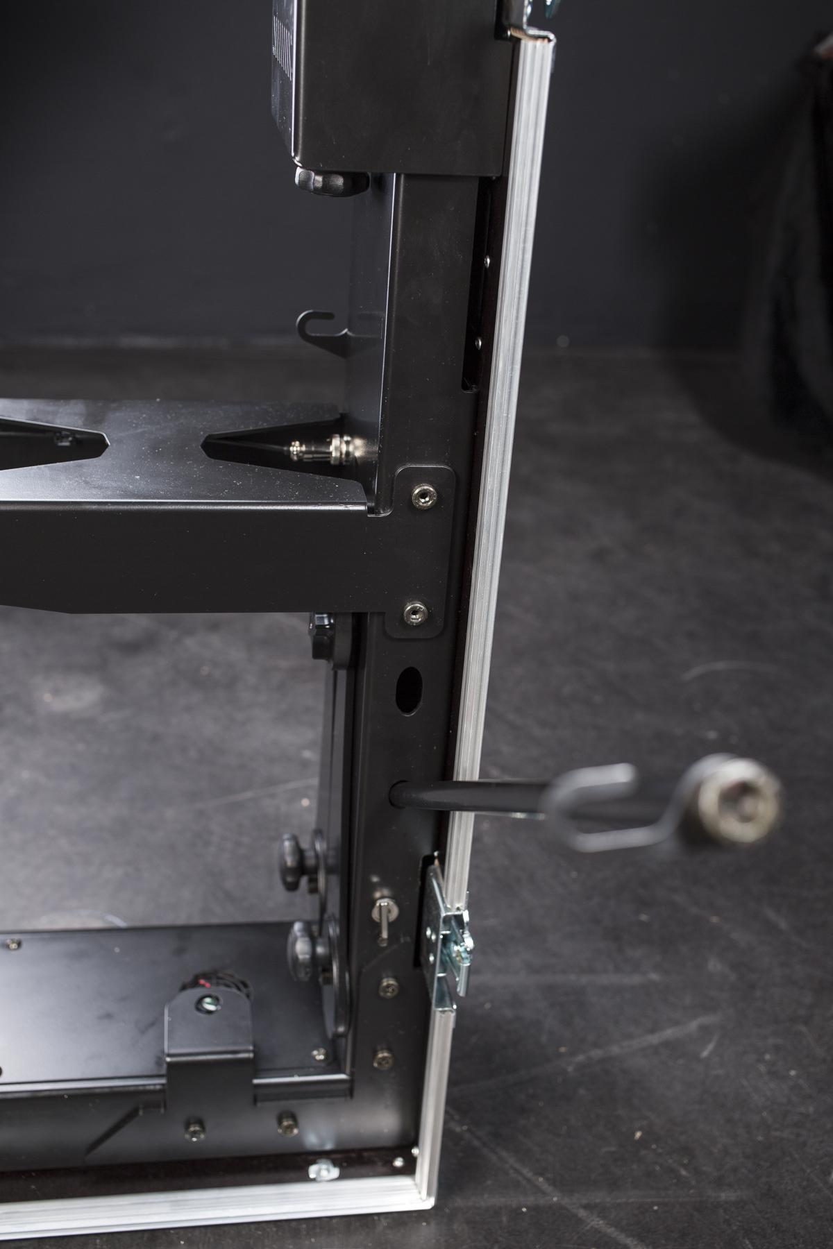
- Insert the short poles with the hook into the holes on both sides in the CASE’s base.
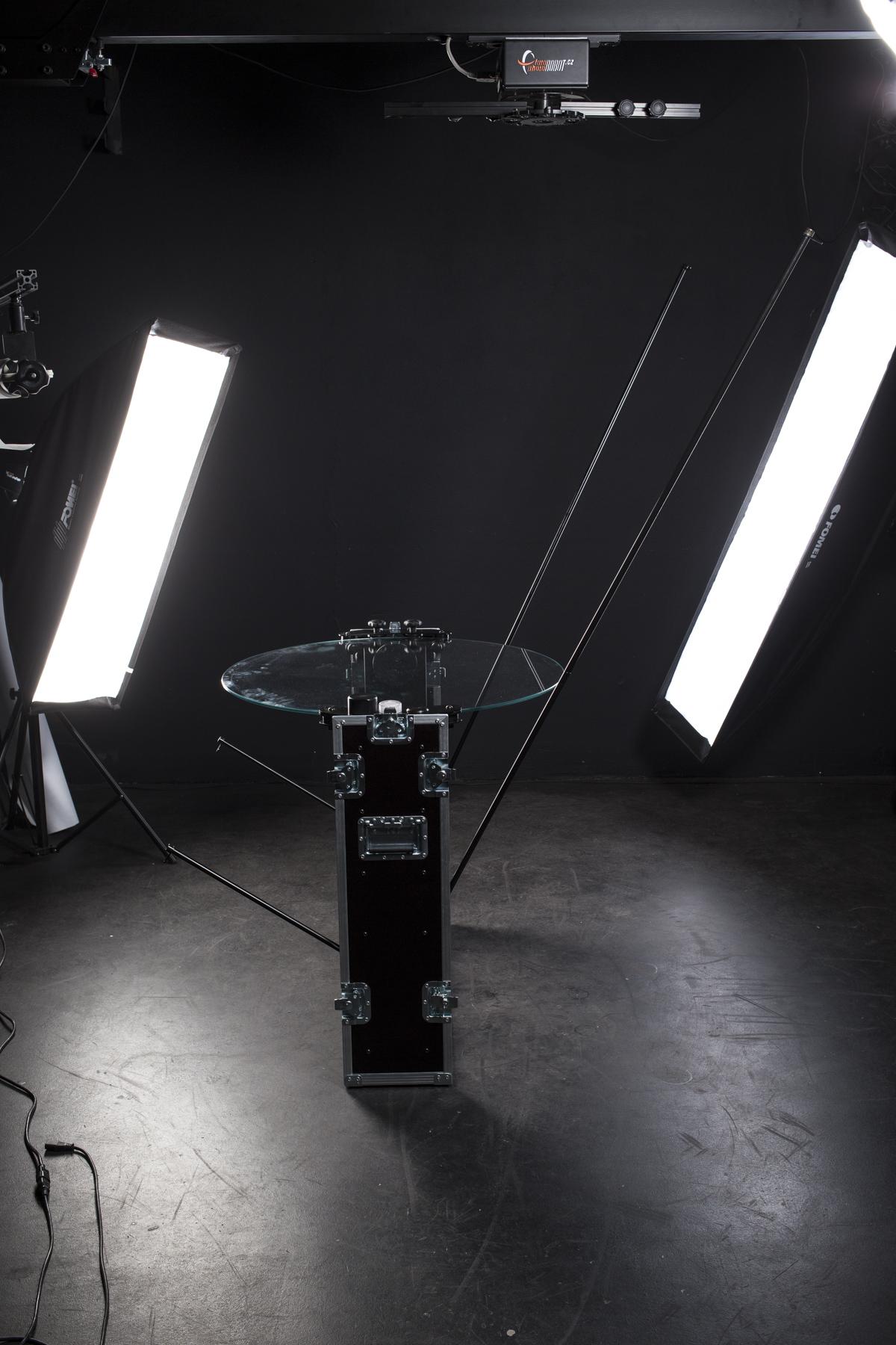
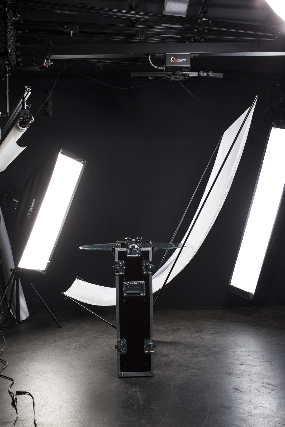
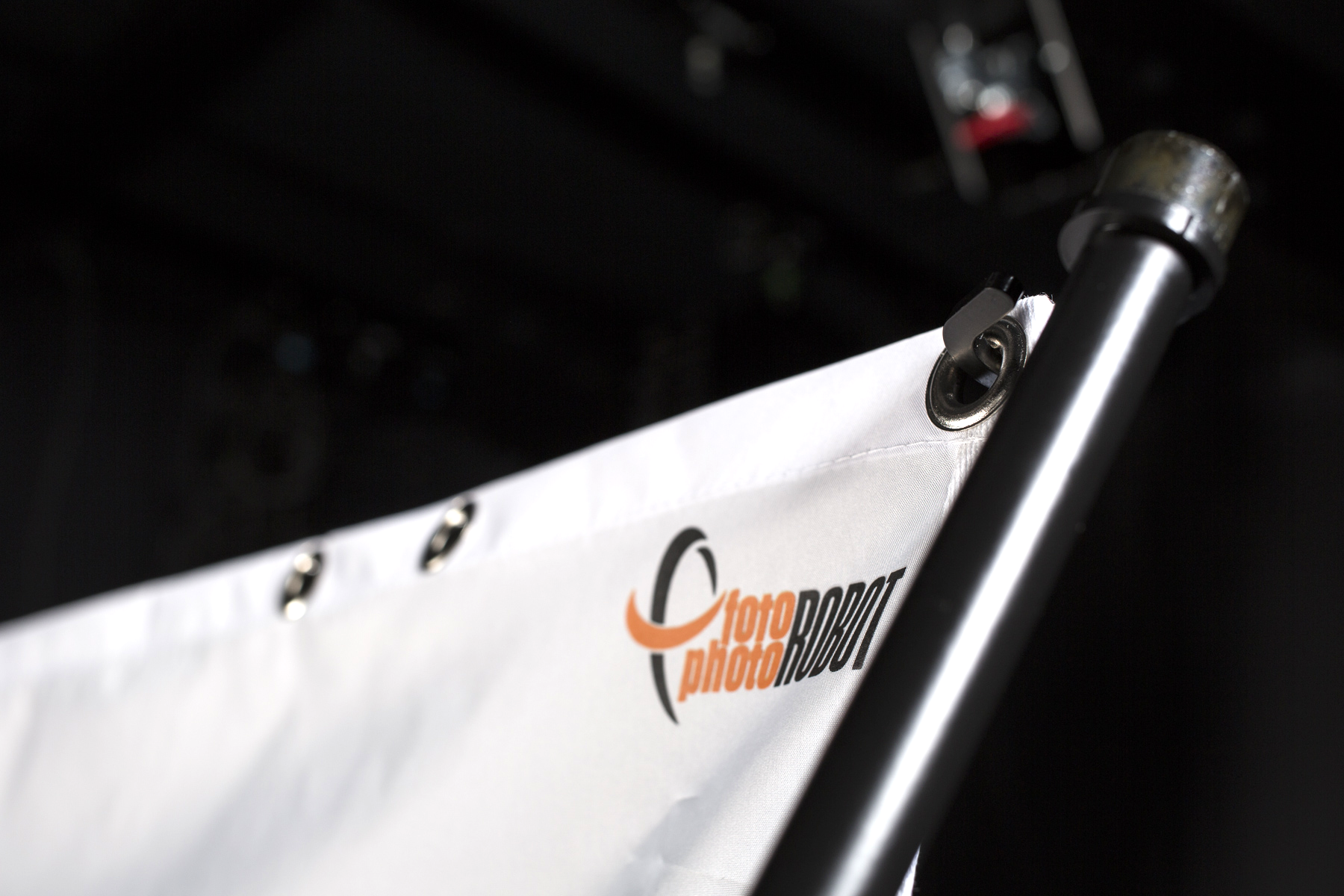
- The photos above show the background poles ready and with the hung background.
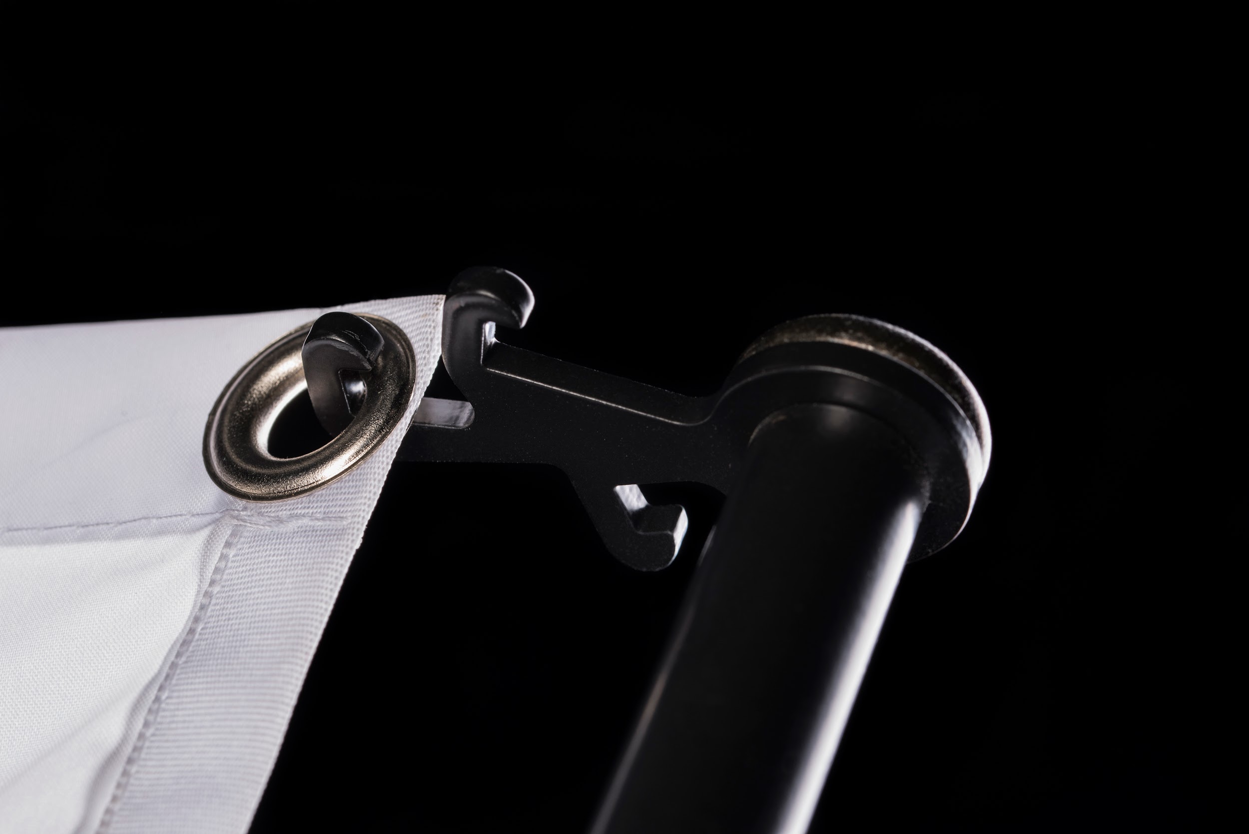
- A triple hook provides easy & sleek background stretching.
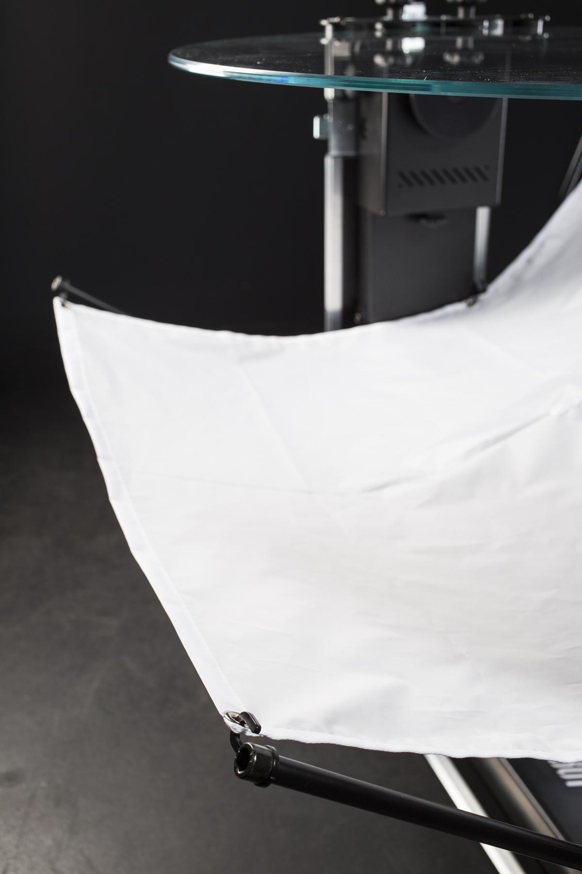
- To hang the background, start with hooking up the top first.
- Next, hook up the opposite end of the background.
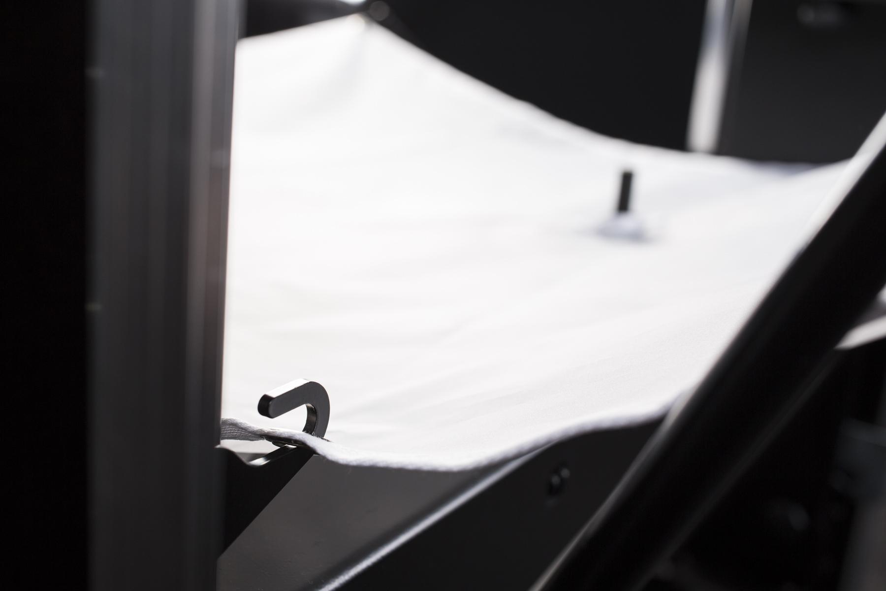
- Then, hook up the background at the CASE’s base.
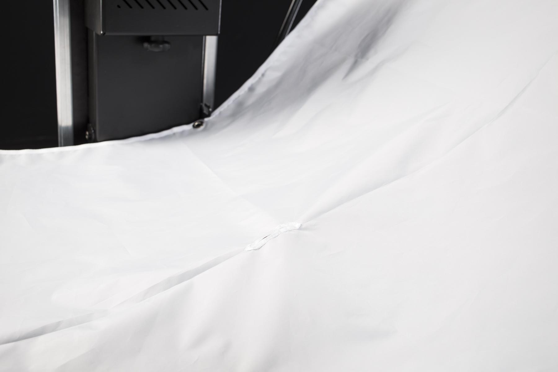
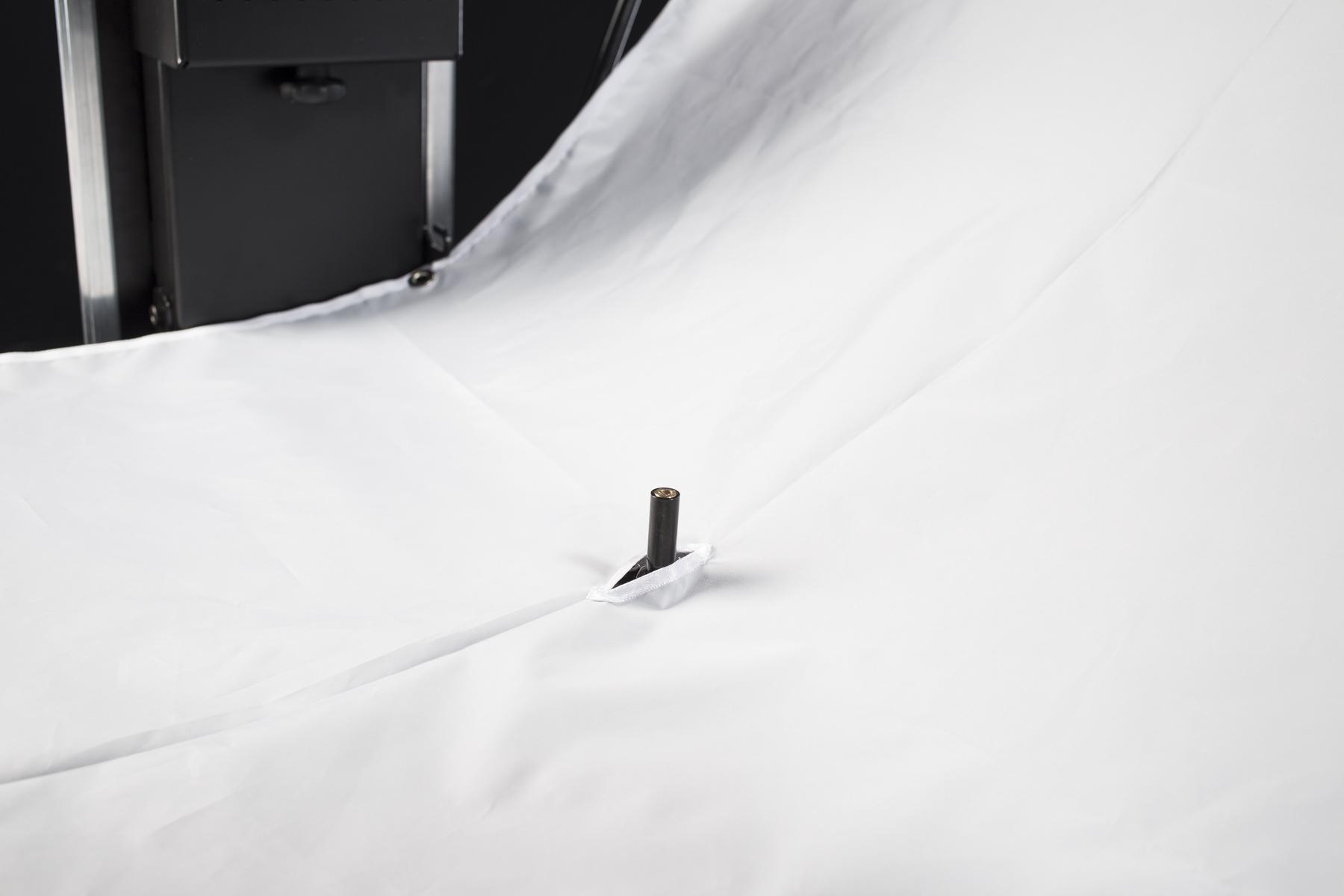
- Finally, ensure the laser is exposed through the slit in the background.
4. Operating the CASE
The CASE is a sophisticated mechanism that requires a basic knowledge of photography for its successful operation. The following chapters provide all the information necessary to succeed.
4.1. Plug in
The CASE is designed to work in 100-240 V mains electricity supply. It uses a standard C13/C14 coupler with either a European, UK or US plug. For safety reasons, it is required to have the CASE switched off while plugging the power cord in.
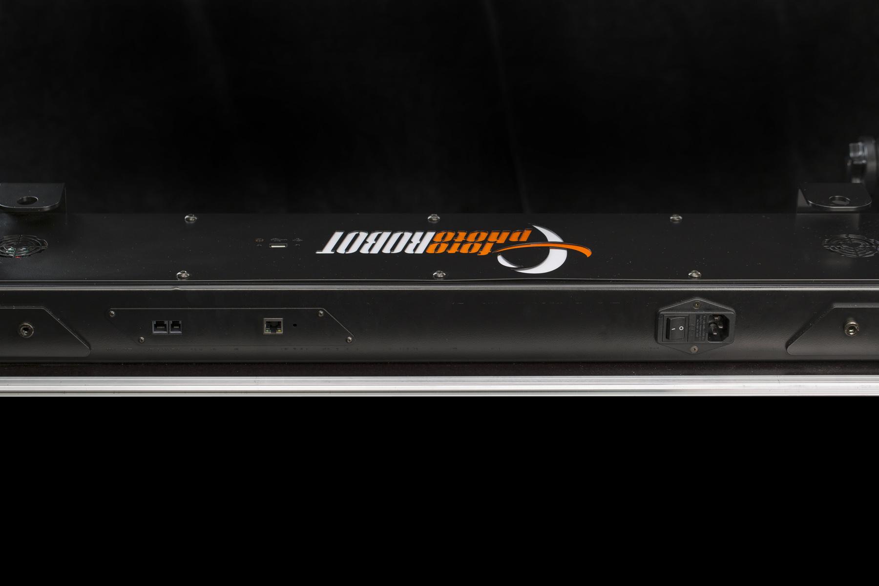
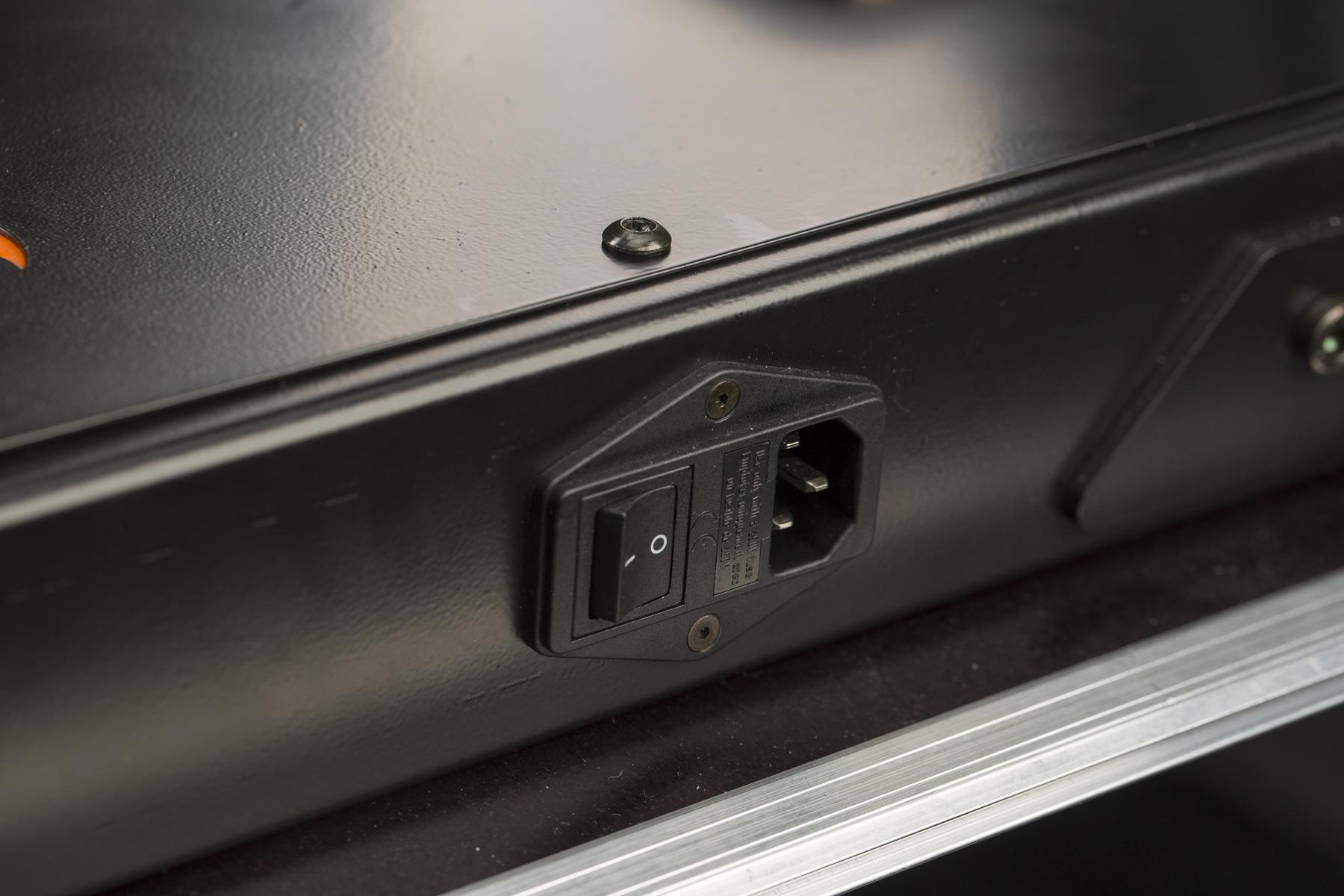
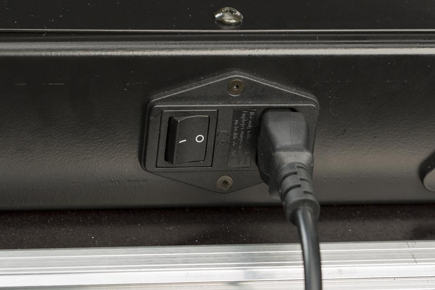
- The power socket is located at the base of the CASE (as in the above 3 photos).
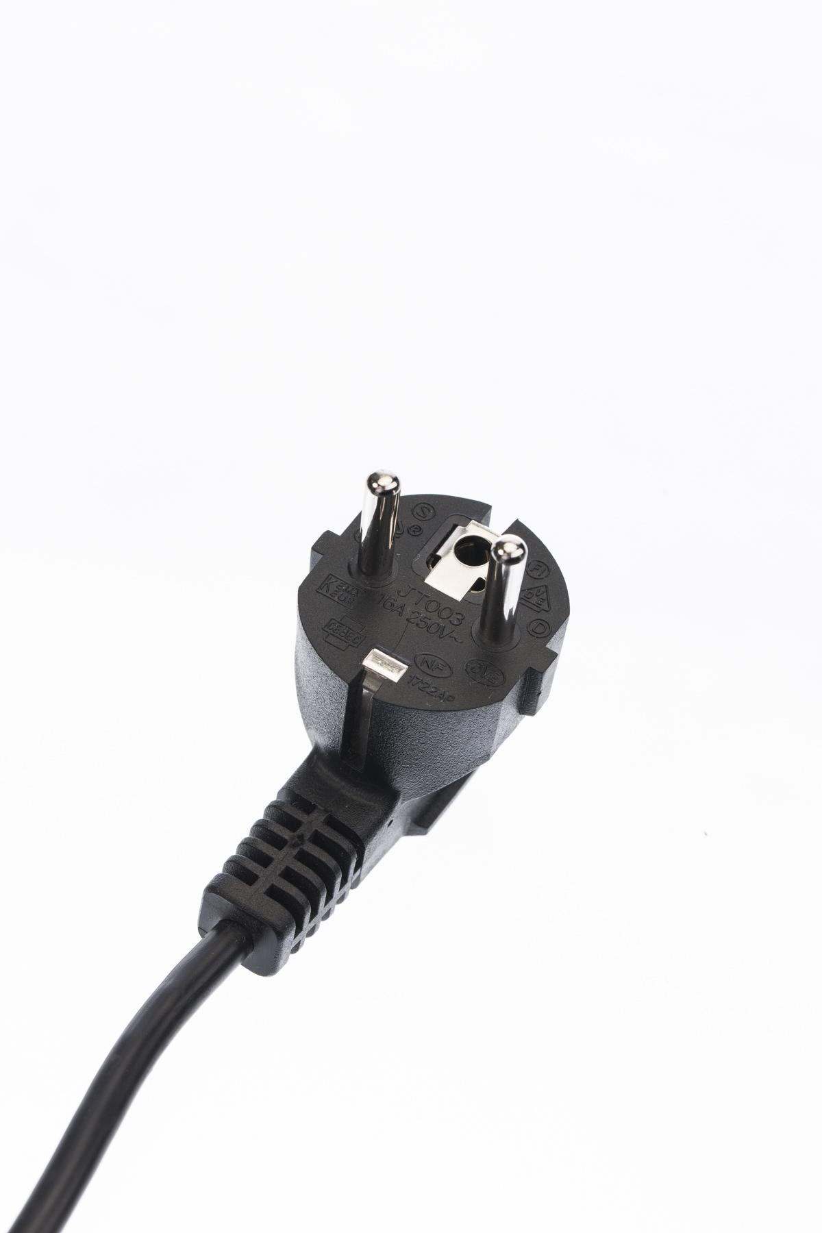
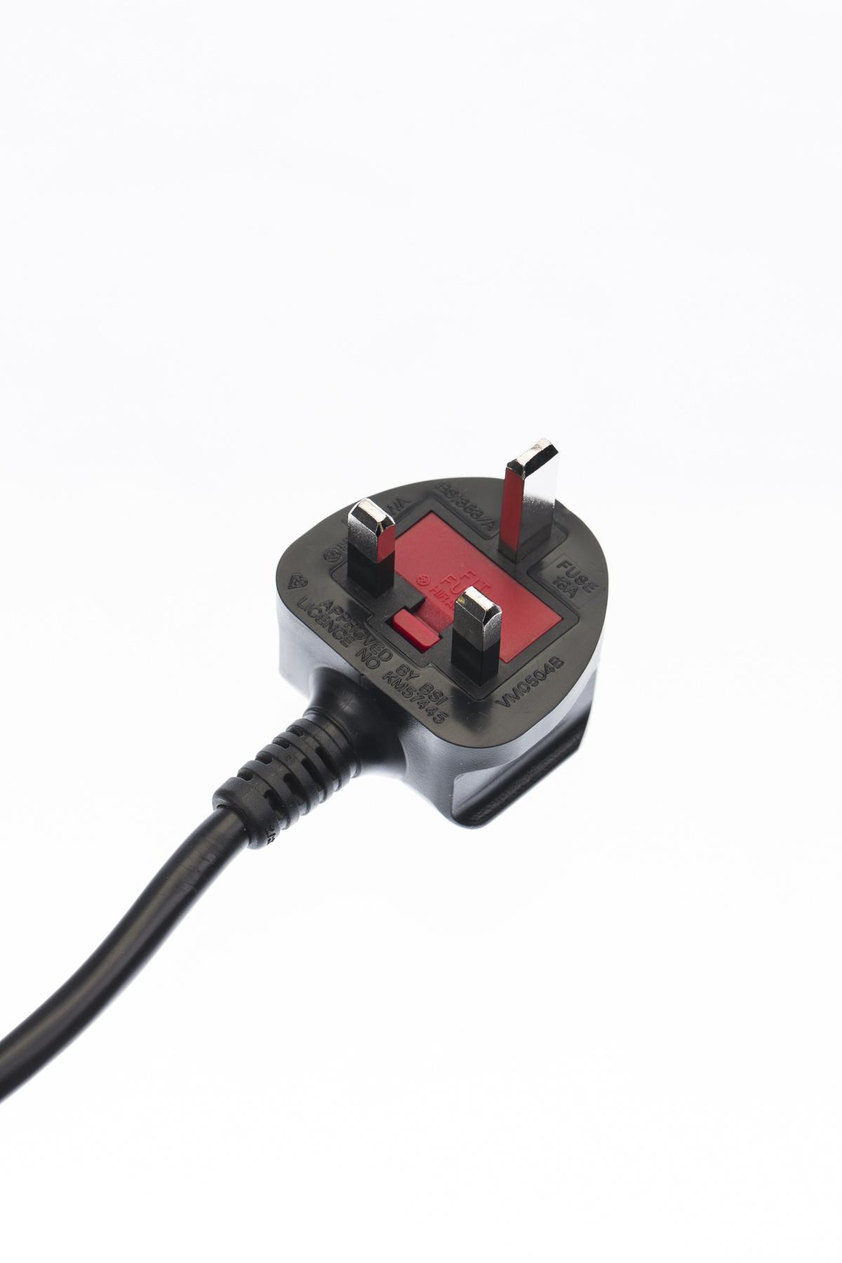
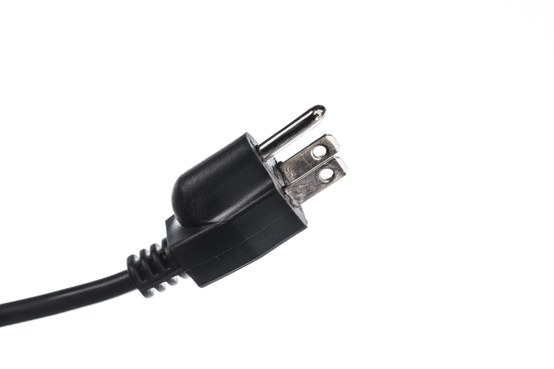
- PhotoRobot will supply EU, UK or US power sockets, depending on your region.
4.2. Turn on
To turn the CASE on, the power switch is located next to the main power socket.

Please NOTE: When turning on the CASE with Wi-Fi connectivity, it takes about 2 minutes to boot the control unit, or 30 secs when connected by LAN.
4.2.1. LED lights indications
Power LED light (red/green > 3 pins)
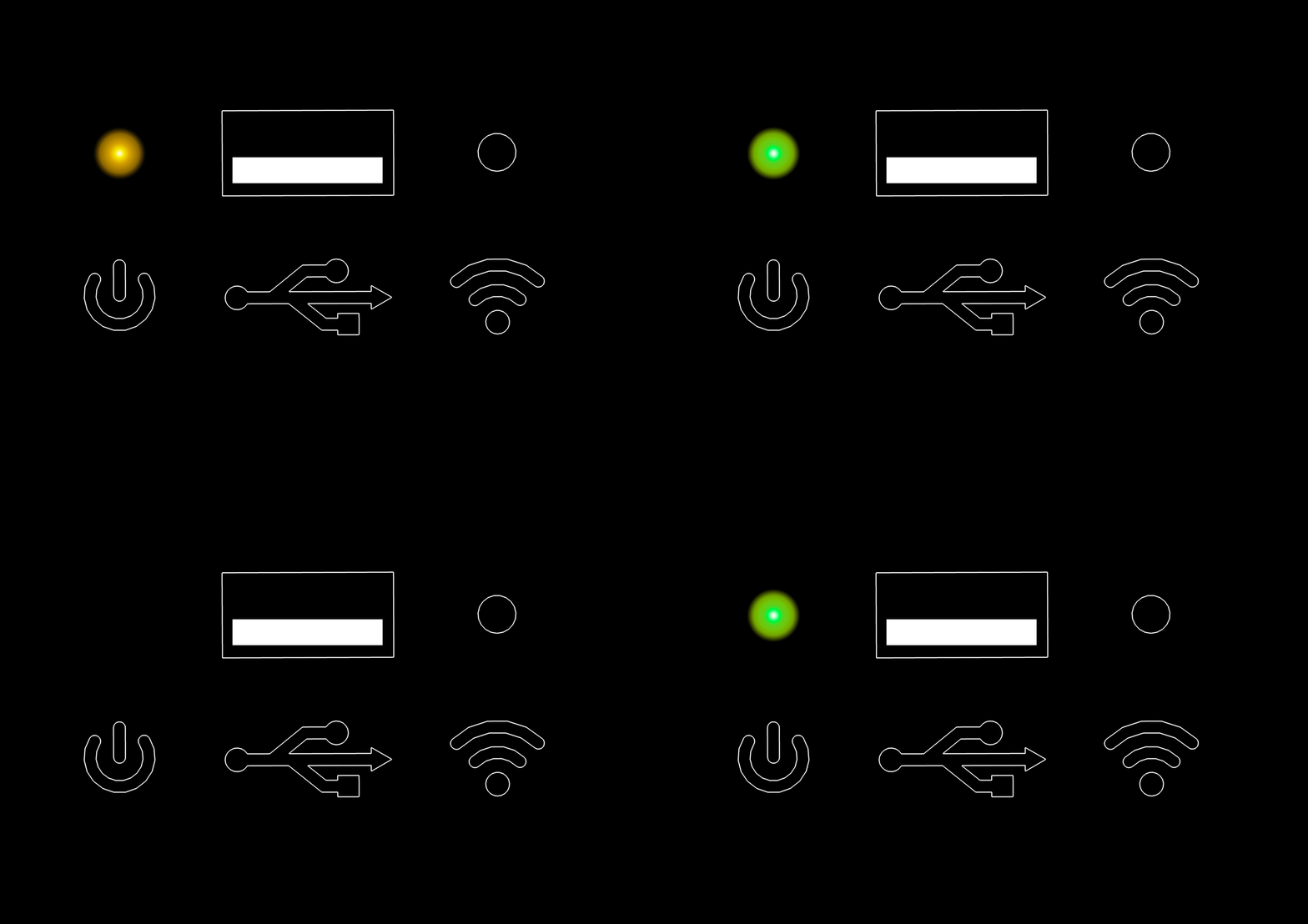
- A yellow light with a green heartbeat pattern means the system is booting.
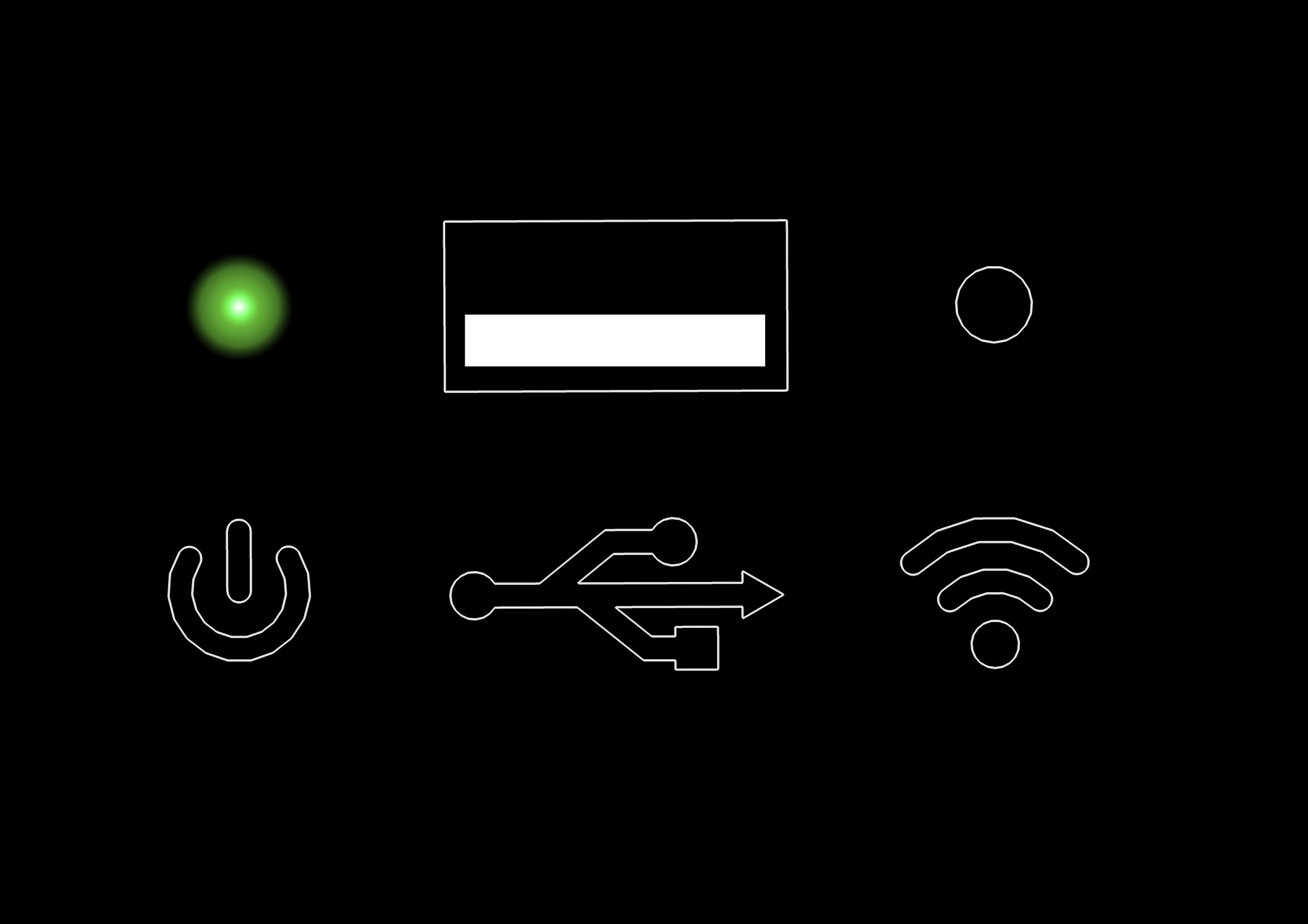
- A green light on means the system is running.
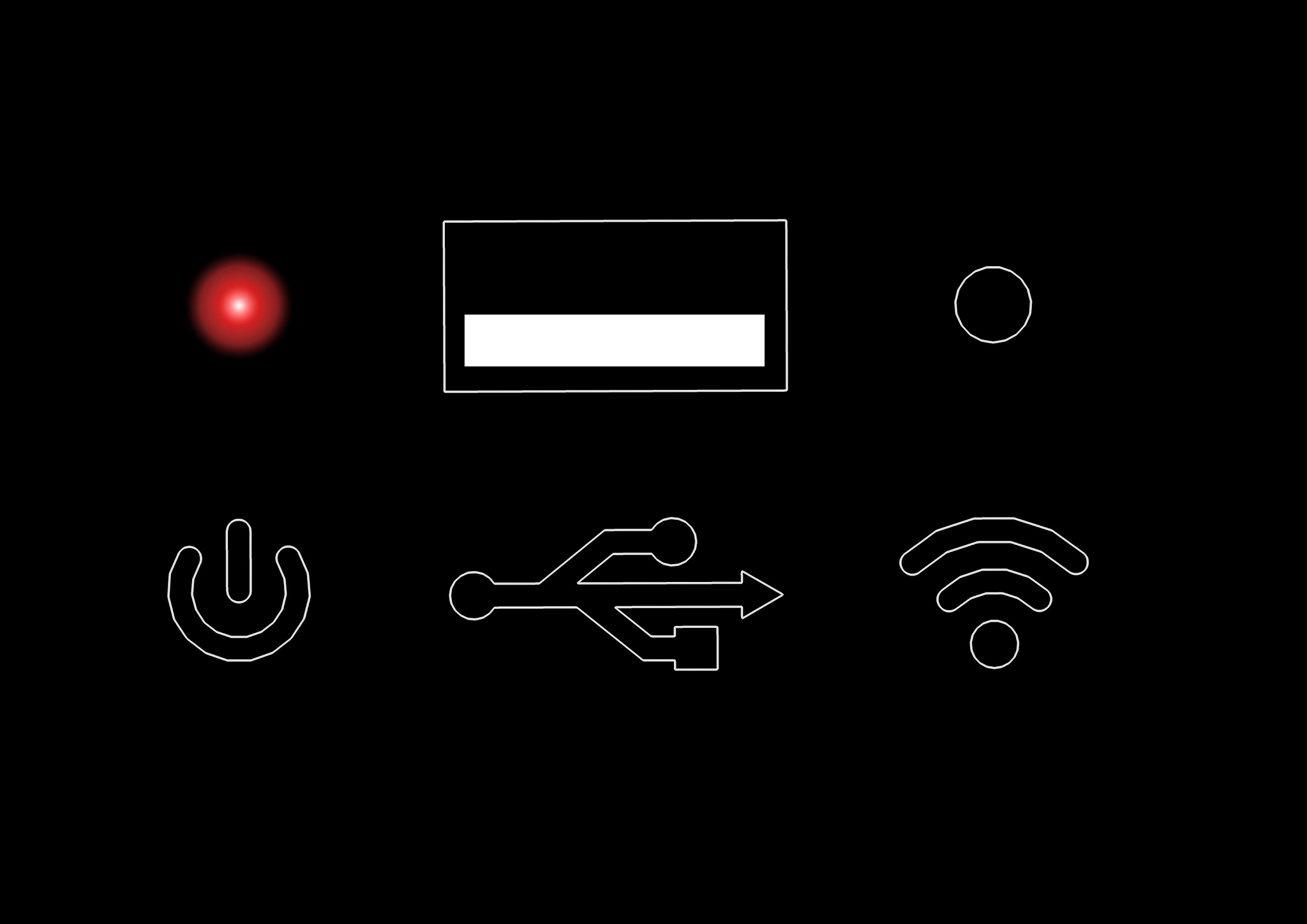
- A red light on means there is a hardware error.
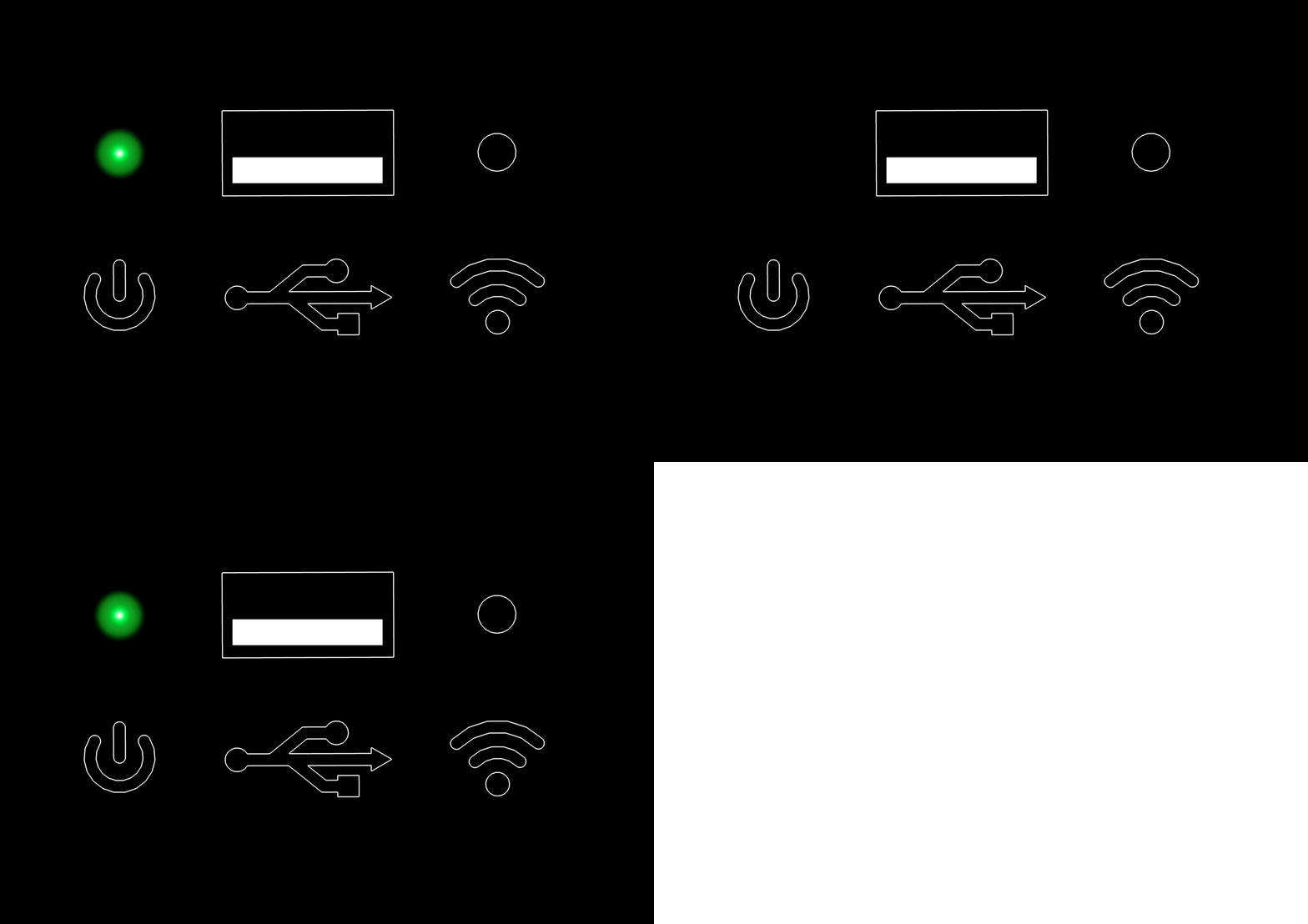
- A flashing green light means the device is moving.
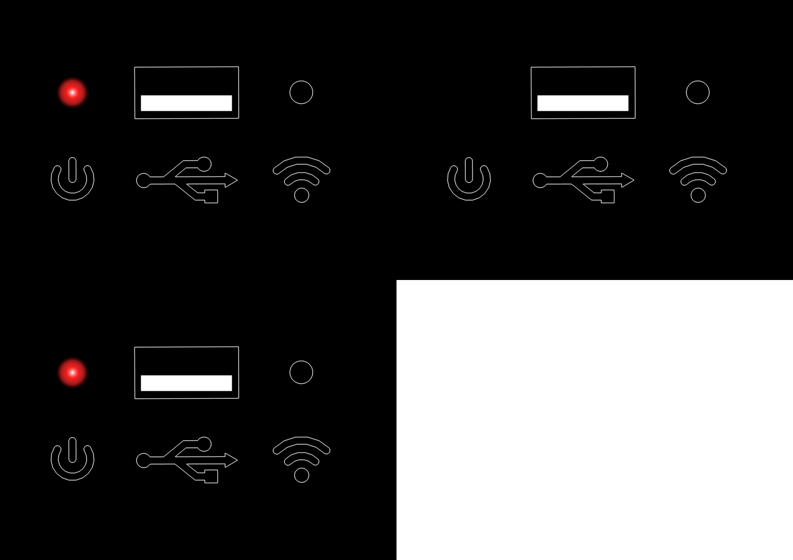
- A flashing red light means ‘not authenticated’.
Wi-Fi LED light (blue > 2 pins)
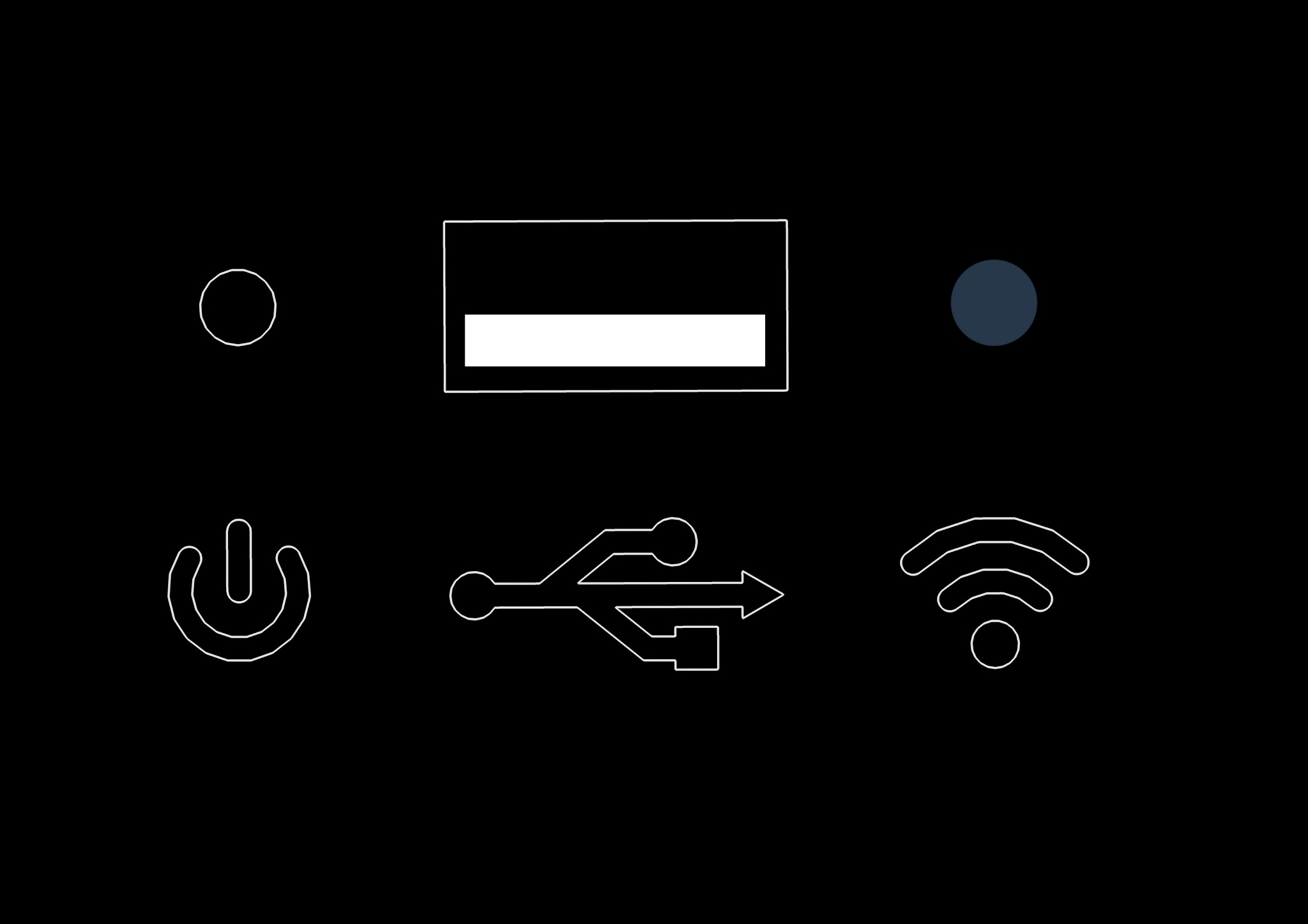
- A blue light off means the Wi-Fi is not connected.
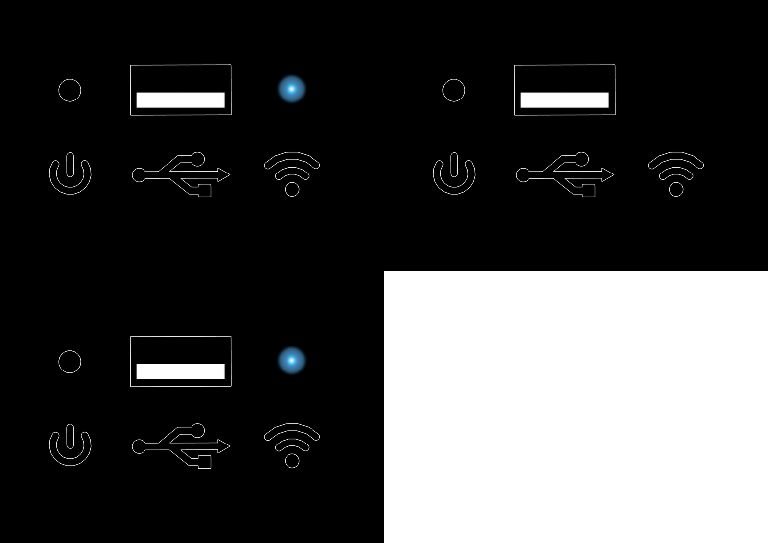
- A flashing blue light means the Wi-Fi is connecting.
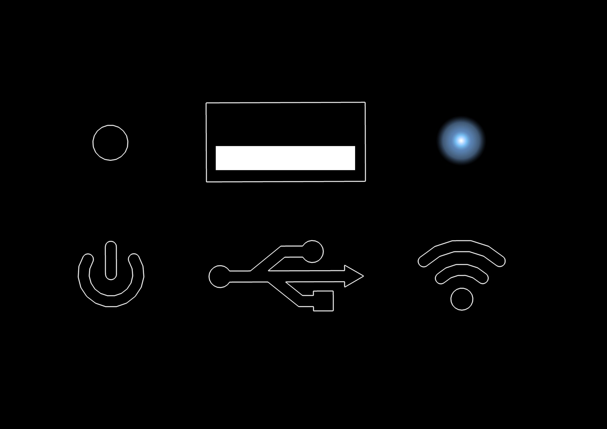
- A blue light on means the Wi-Fi is connected.
4.3. Connect
The CASE is built around the latest generation of the PhotoRobot control unit, operated by PhotoRobot Controls — our software released primarily for macOS and also for Windows (although, we recommend macOS for the best experience). A companion app, PhotoRobot Touch, can act as a wireless camera for the macOS version. Advanced integrators may alternatively control the unit directly through its API. To operate the CASE, it must be connected via either LAN or a wireless network so the controlling app can communicate with the robot. The CASE can also establish its own Wi-Fi network through the USB module. An internet connection is not necessary for operating the CASE, but internet is required for updating the firmware. The following chapters describe how to connect the CASE.
4.3.1. Browser-Based User Interface App
The browser-based user interface application is a part of the CASE’s integrated control unit. It can be accessed from the web browser on any device. It does not have the capability to adjust camera and lighting settings, but it adds exceptional mobility and flexibility to robotized photography. To connect the CASE to the Browser User Interface, both the CASE and the controlling device must be present in the same network via either a LAN, WLAN or Wi-Fi network provided by the Wi-Fi module plugged into the CASE.
Note: The browser-based interface is a service interface — it is not intended for production photography. With a machine API license, this behavior can be extended to allow production image capture through the service interface.
4.3.1.1. LAN
The CASE has an integrated 8P8C (RJ45) socket to connect the CASE using a standard ethernet cable.
- Find the 8P8C (RJ45) socket for the network connection located at the bottom of the CASE’s base.
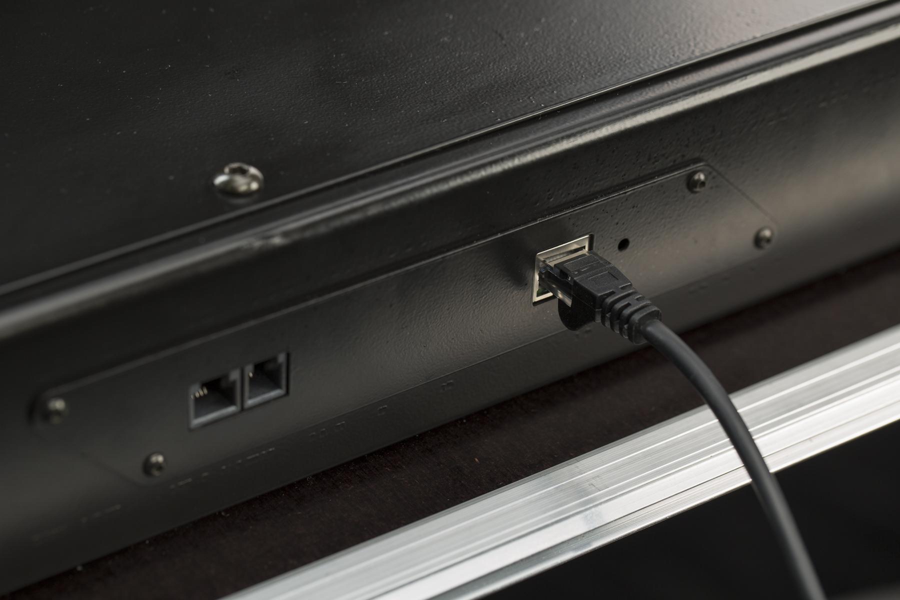
- A standard ethernet cable can be used to connect to the CASE.
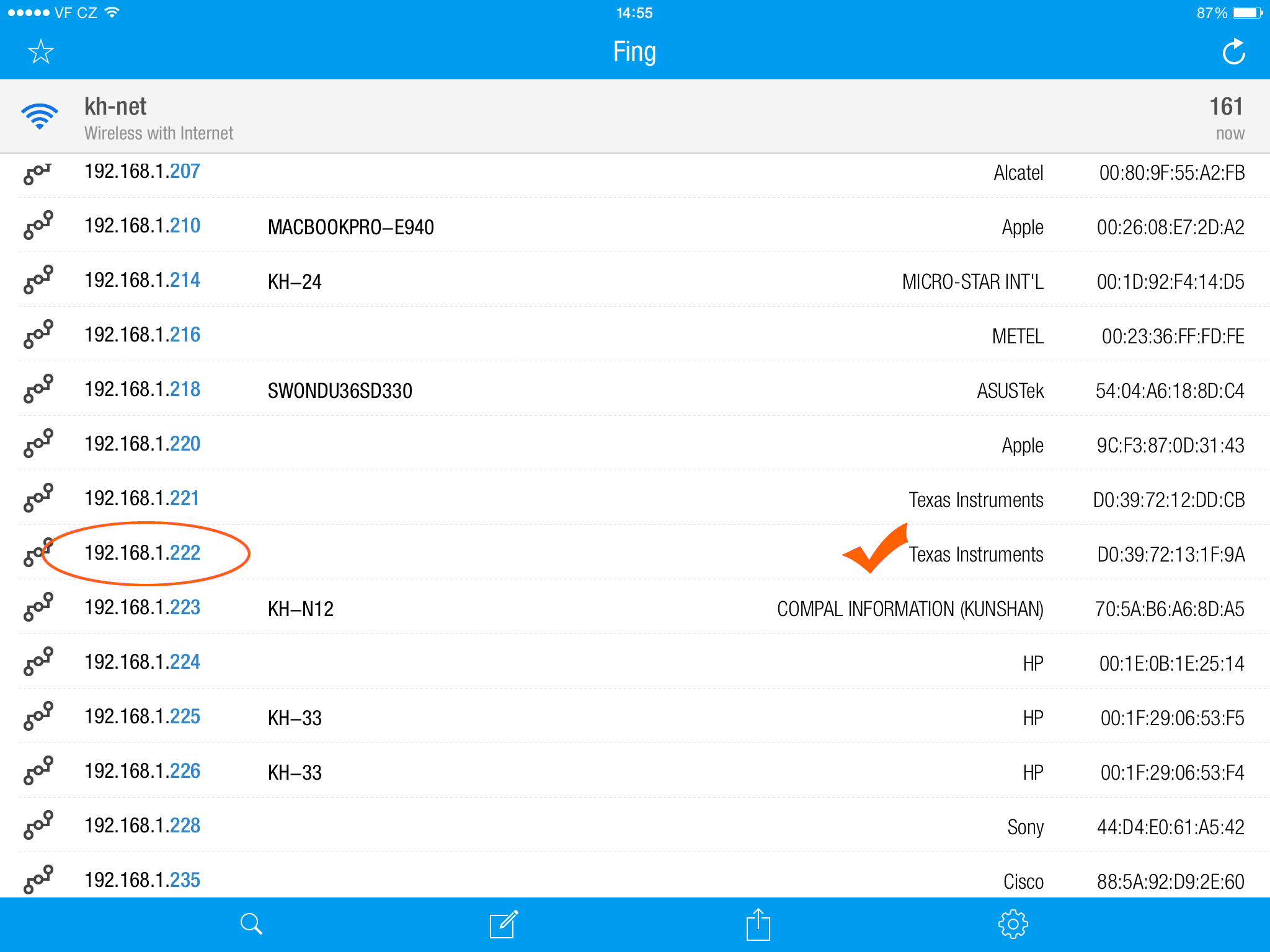
- It is necessary to find the IP address of the CASE to connect it to the Browser-based UI App. You can use any IP scanner, such as the Fing mobile app. In the IP address list, search for “Texas Instruments” (example above).
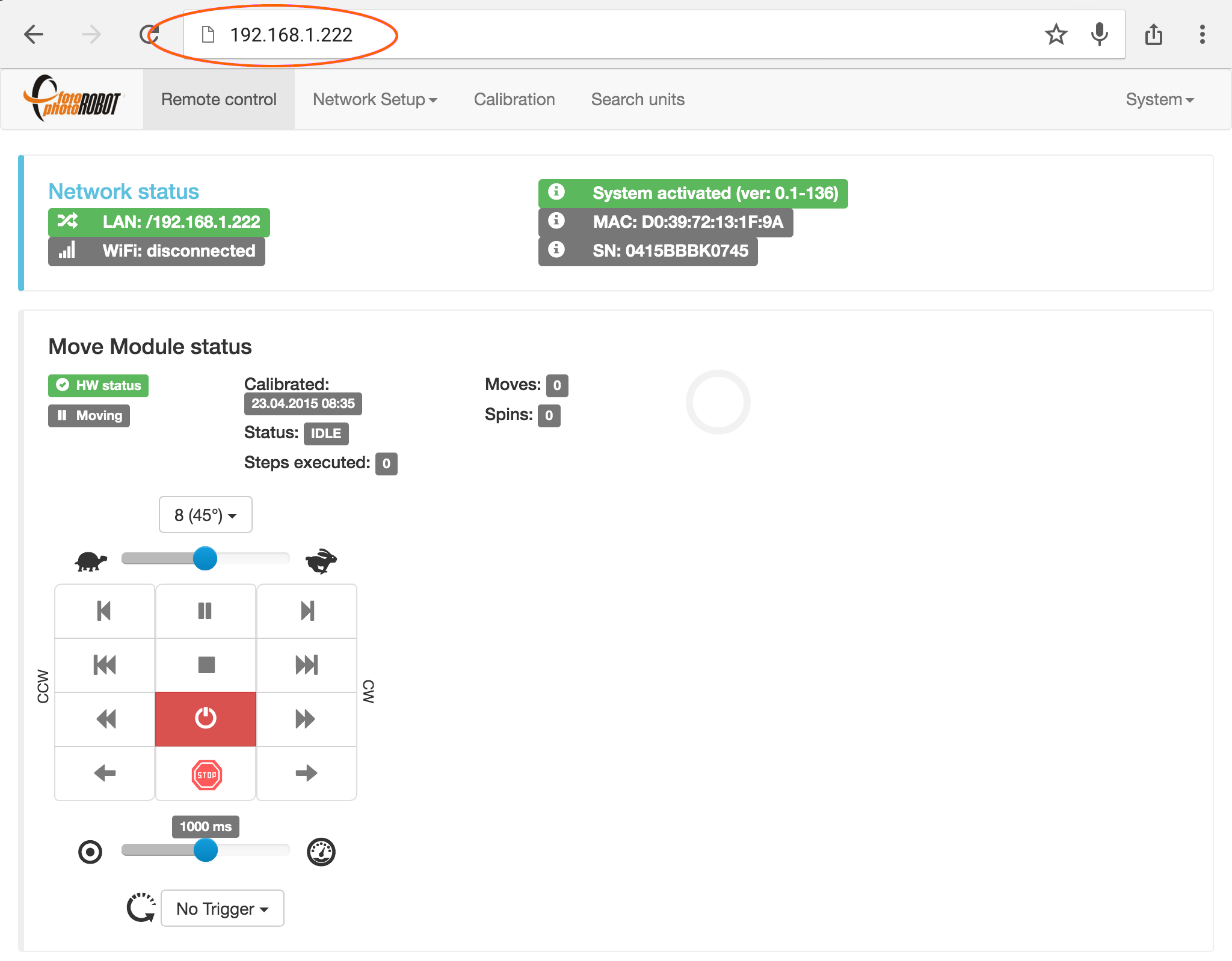
- To launch the Browser-based UI App, input the IP address of the CASE into any web browser. To learn more about controlling the CASE using this application, please refer to chapter 4.9.2 - Control the CASE.
4.3.1.2. Wi-Fi network created by the CASE (AP mode)
To create the CASE’s own wireless network, it is necessary to use the USB Wi-Fi module available as an optional accessory.
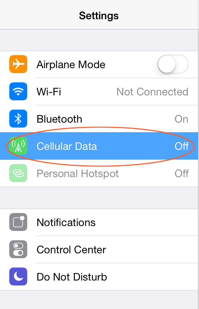
- Note: It may be necessary to turn off the cellular data in order to connect your device to the CASE via Wi-Fi.
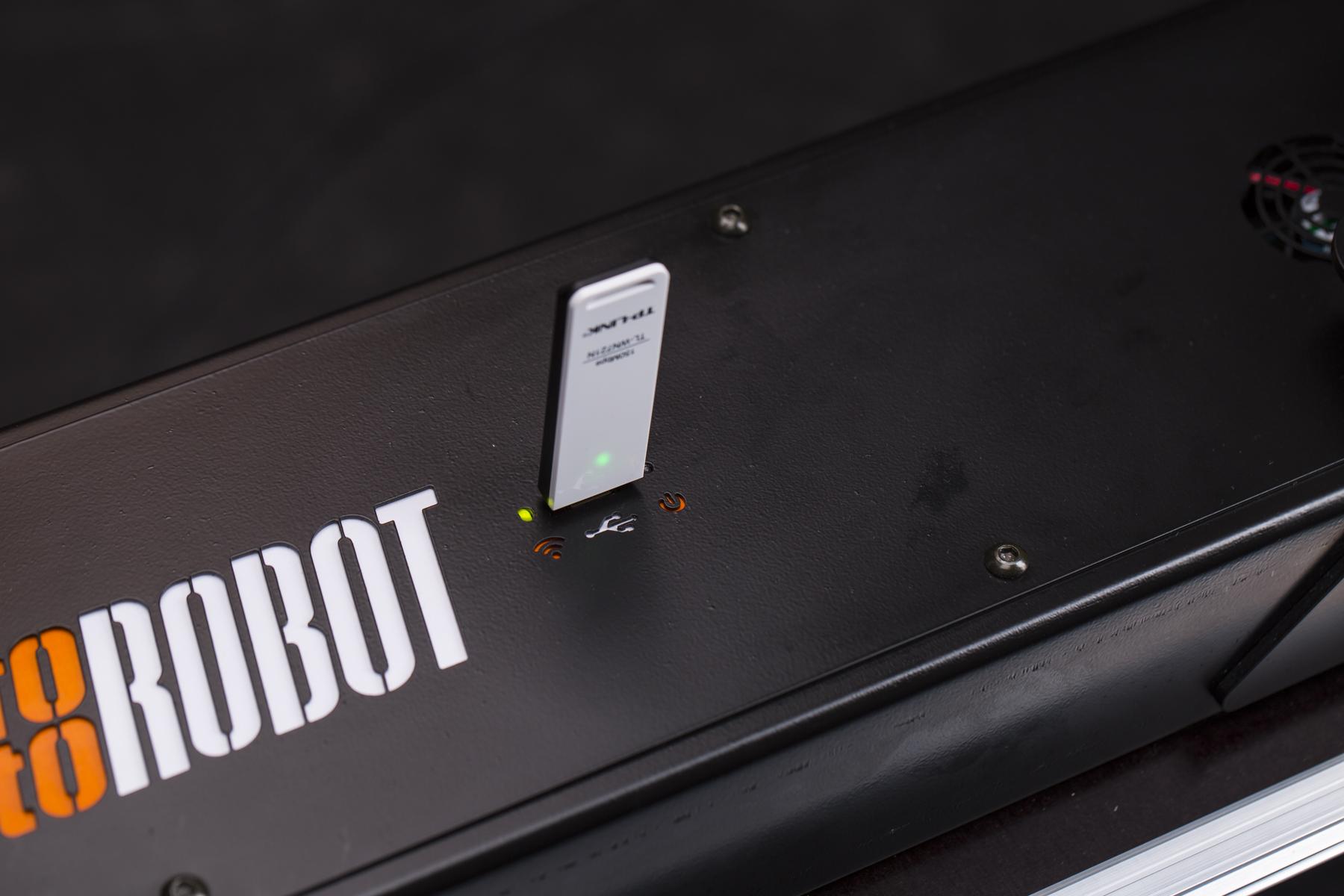
- Plug the Wi-Fi module into the USB socket of the CASE which is located on the top side of the machine base. Successful initiation will be indicated by the green LED blinking.
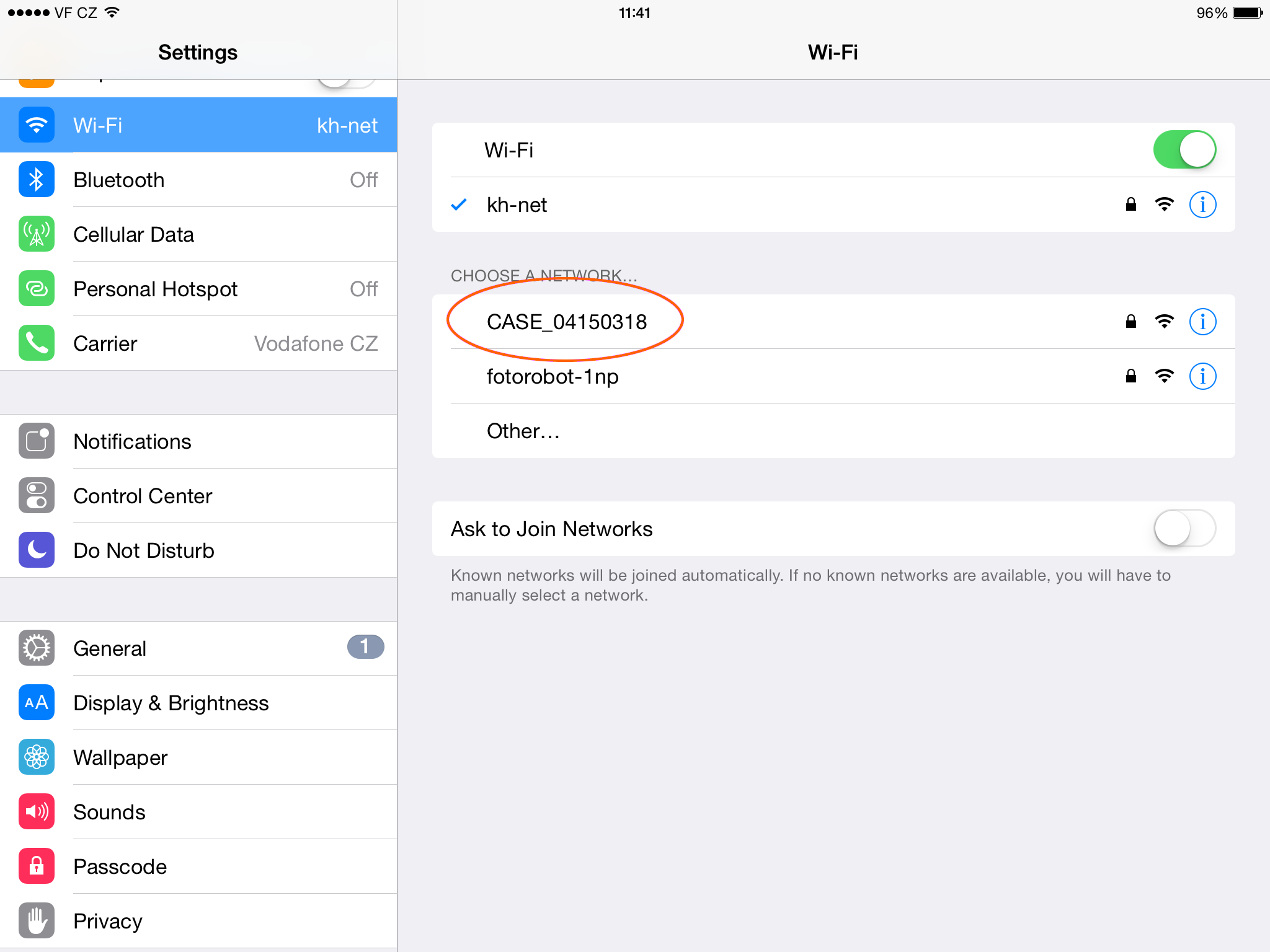
- Search for the Wi-Fi network named “CASE_SerialNumber” on your computer or mobile device.
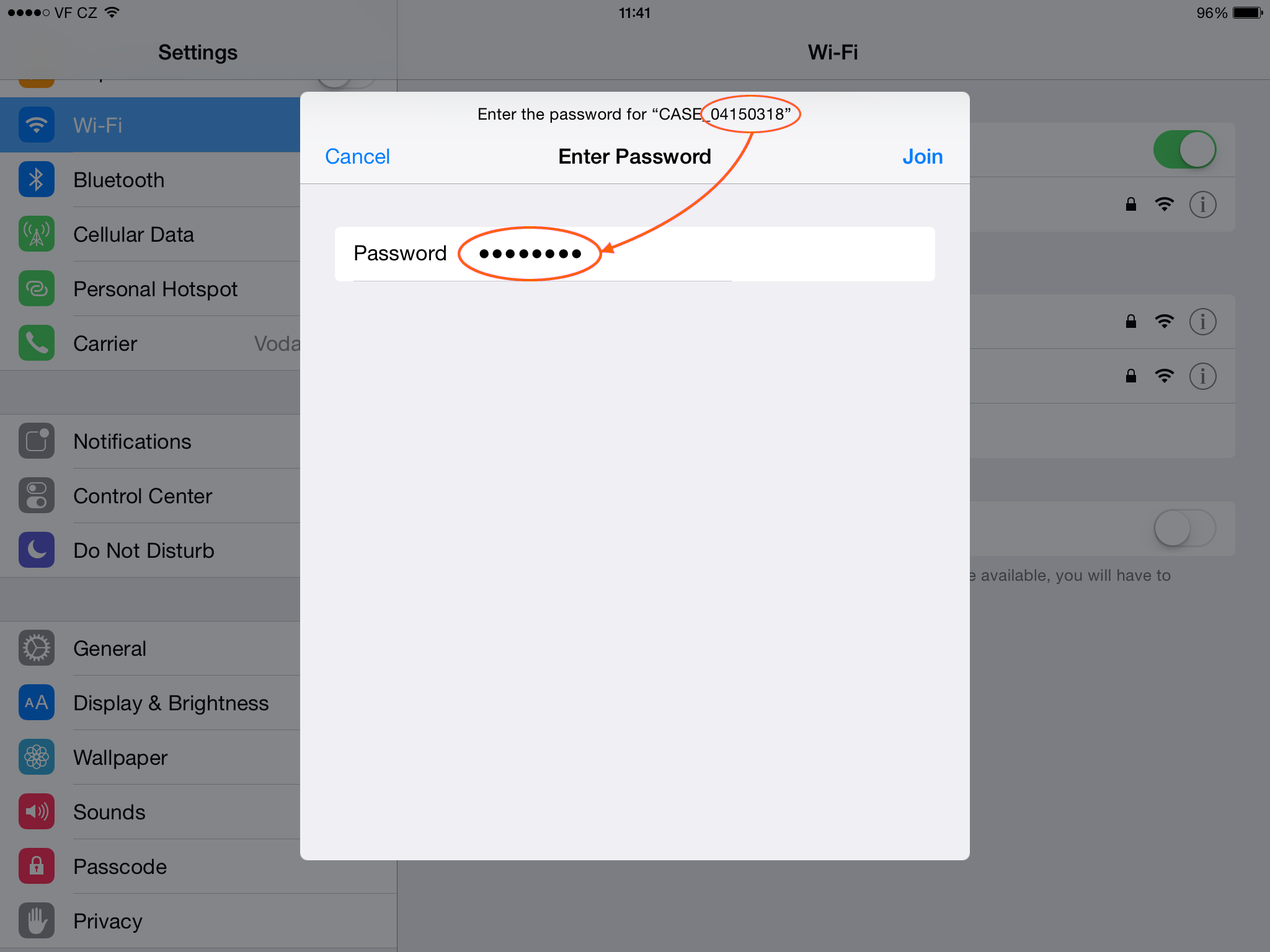
- To connect to the network “CASE_SerialNumber”, use the SerialNumber as a password (in the above example: 04150318).
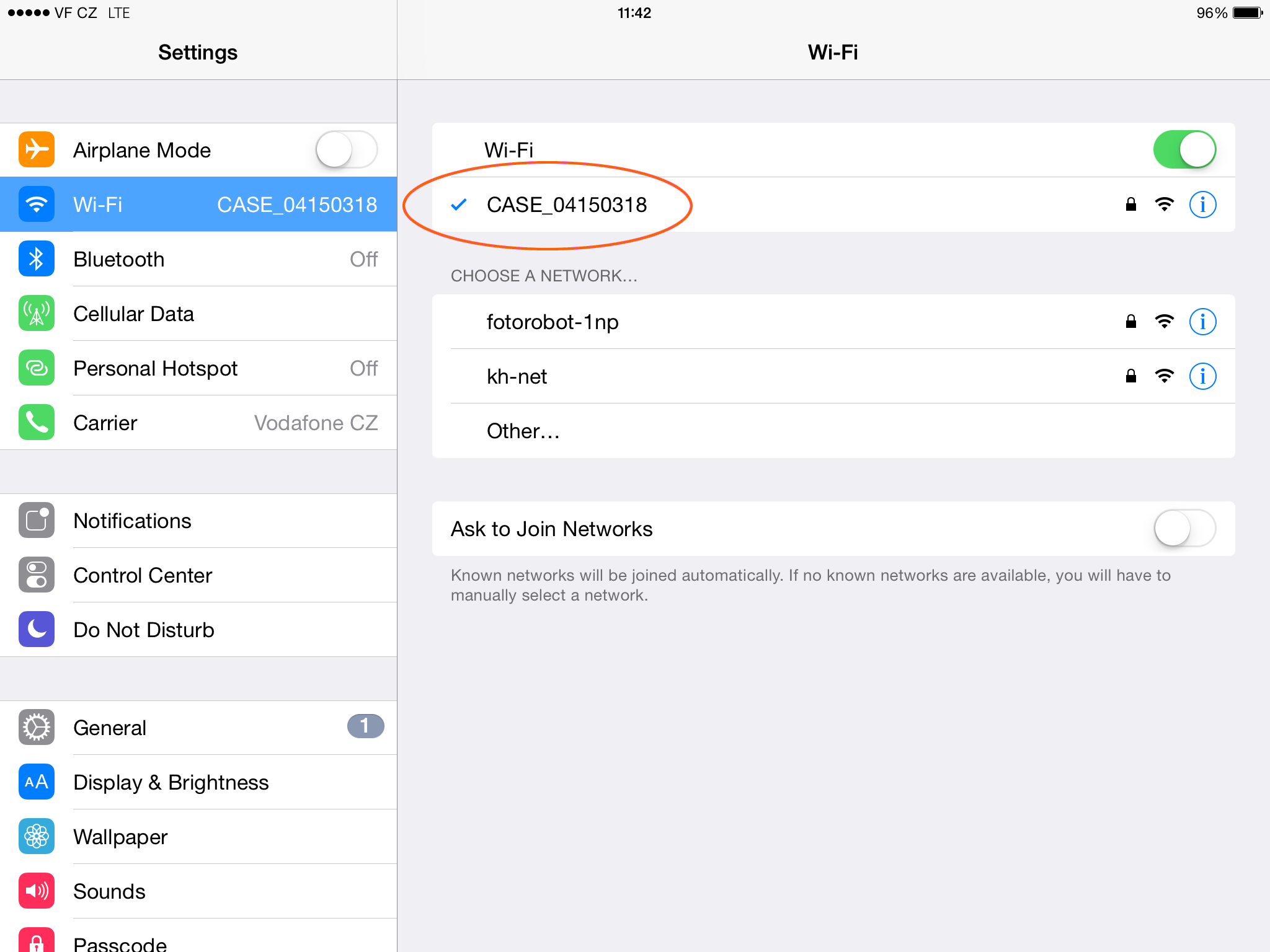
- When the CASE’s Wi-Fi is connected to your device, you are ready to start controlling the CASE. By default, the CASE Wi-Fi is broadcasting at channel No. 9.
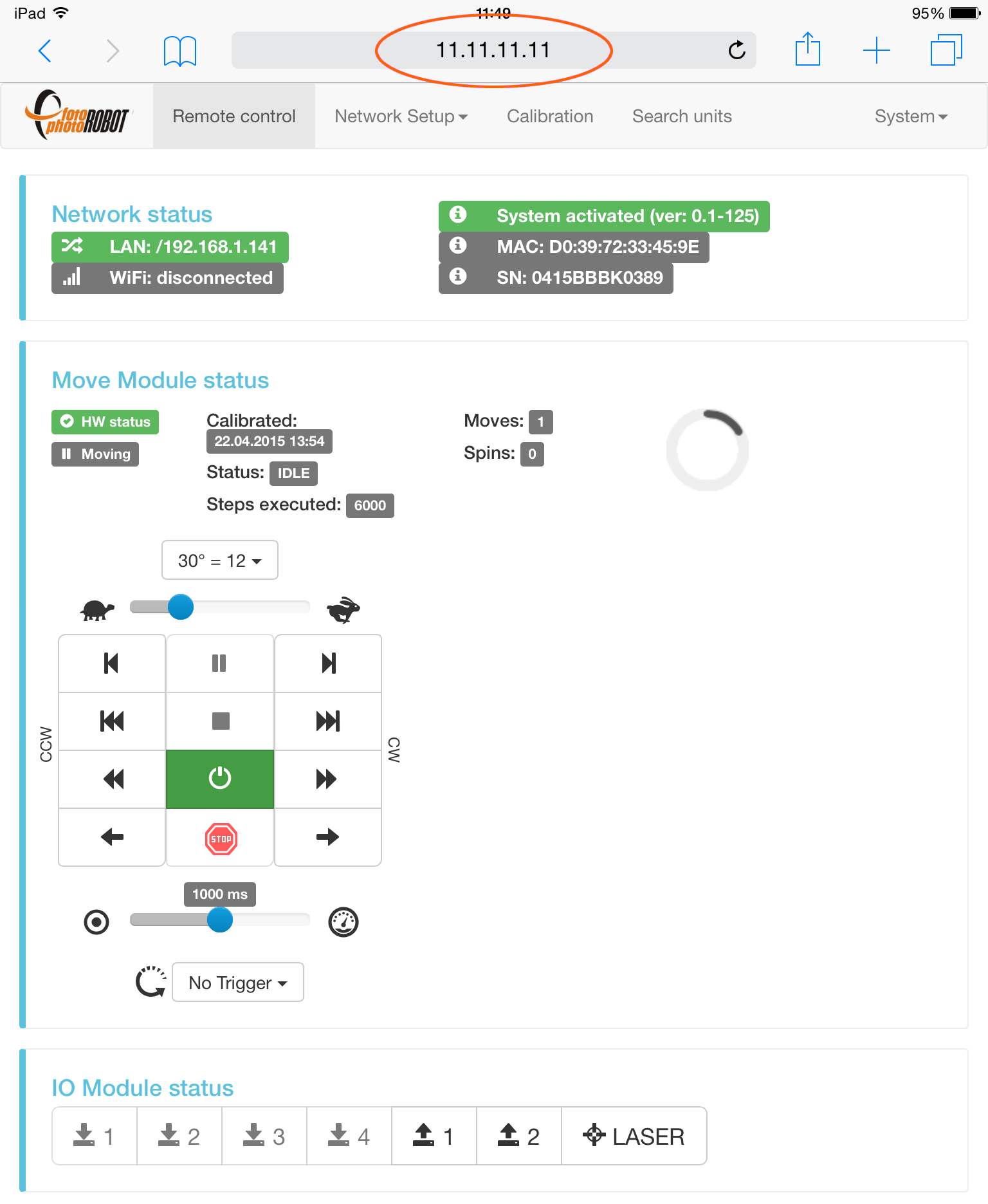
- To launch Web-based User Interface App, type 11.11.11.11 to your browser’s address window. To learn more about controlling the CASE using this application, please refer to chapter 4.9.2 - Control the CASE.
NOTE: When turning on the CASE with the Wi-Fi connectivity it takes about 2 minutes to boot the control unit.
4.3.1.3. Existing Wi-Fi network (client mode)
You can connect the CASE to an existing wireless network using the USB Wi-Fi Module from the optional accessories. This way, your controlling device (e.g. computer or mobile device) can operate the CASE and stay connected to your regular network to access the internet, printers, NAS drives and other network peripherals.
To do this, you first need to connect to the CASE’s Wi-Fi network provided by the USB module. This procedure is described in the previous chapter 4.3.1.2 -Wi-Fi network created by the CASE.
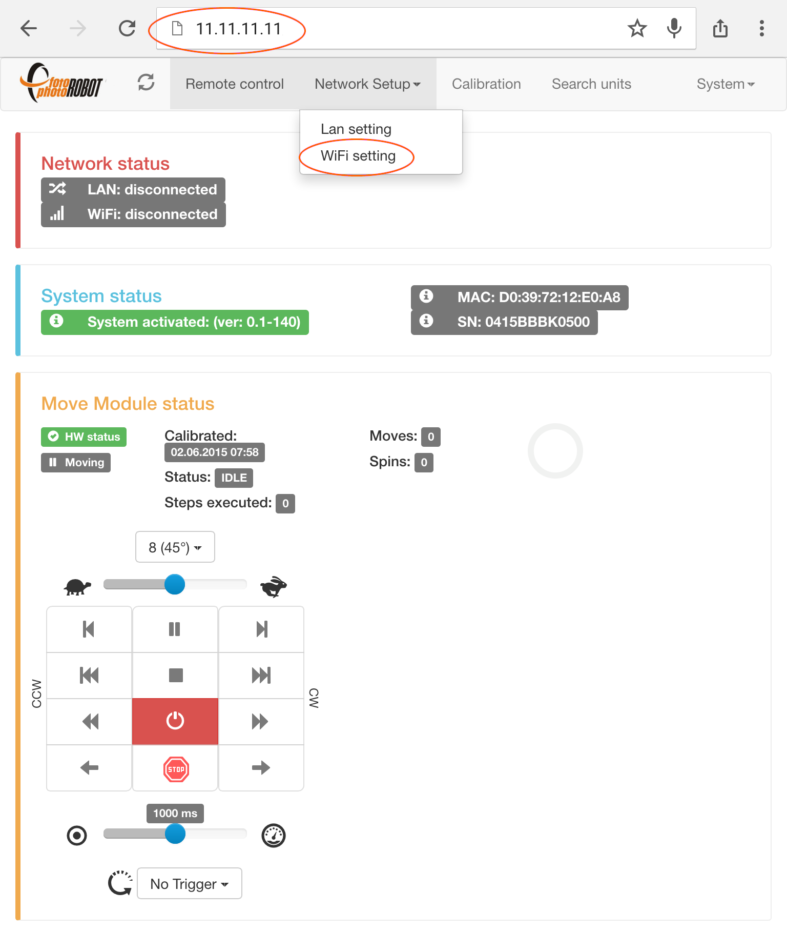
- After you are connected to the Wi-Fi provided by the USB module plugged into the CASE and the web-user interface is launched via IP address 11.11.11.11, go to Wi-Fi settings in the Network Setup menu.
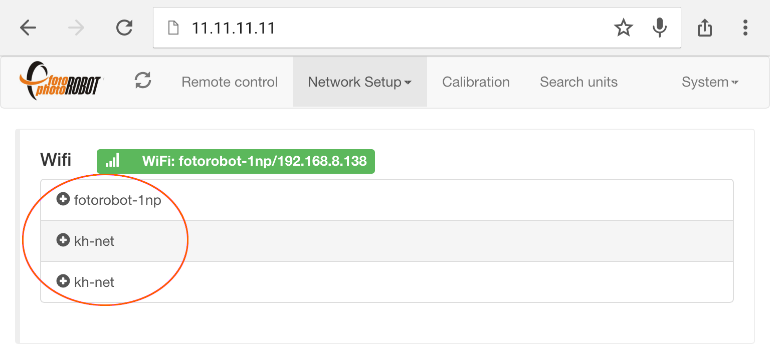
- In the list of wireless networks, choose the network which you wish to connect to the CASE.
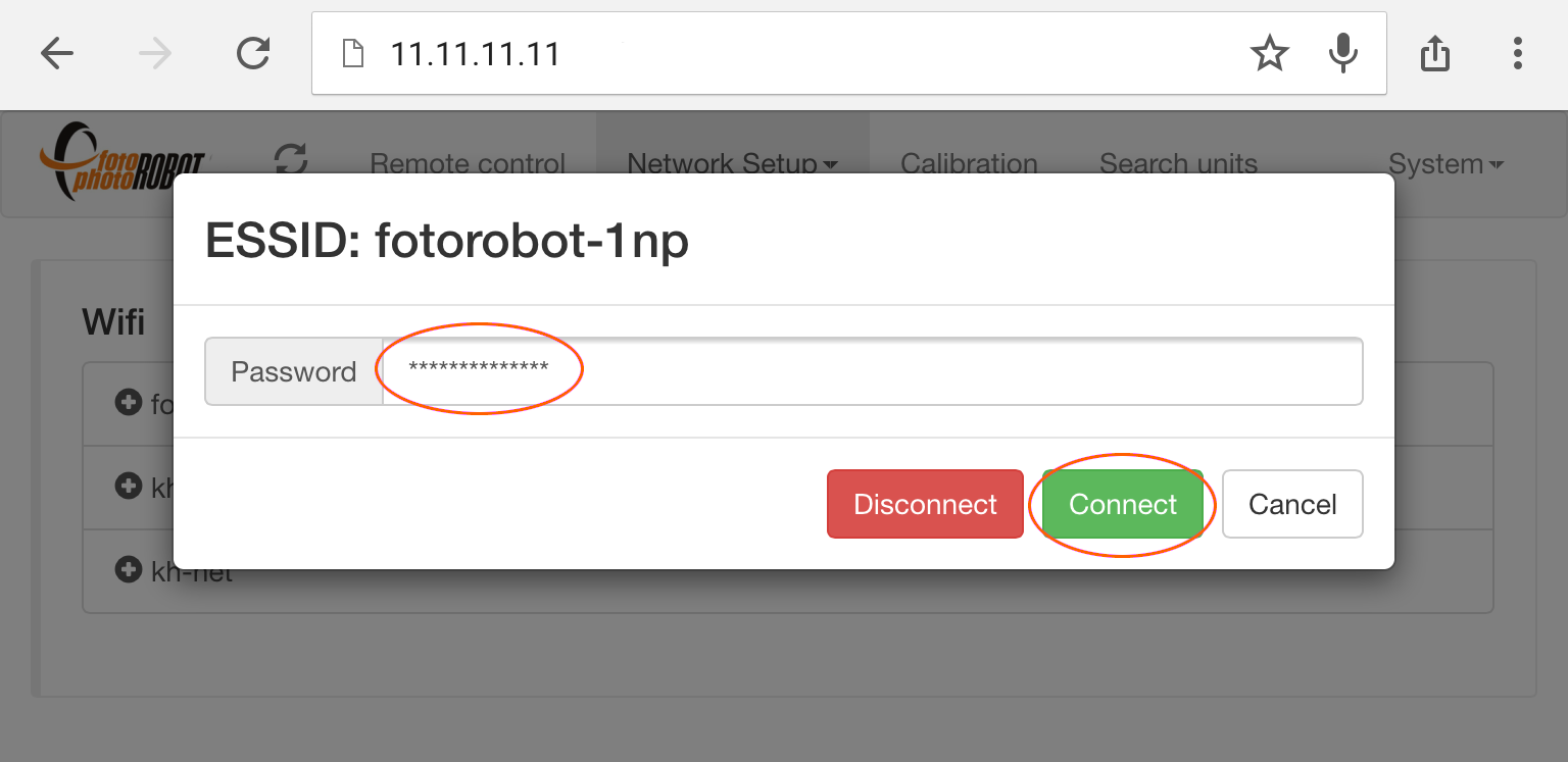
- Next, type in the password of your selected wireless network.
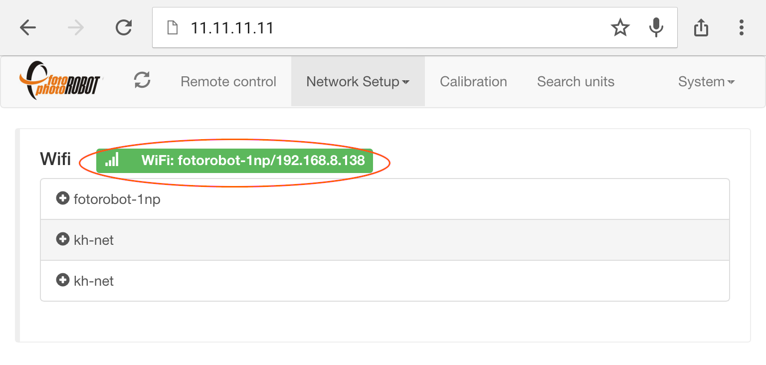
- In the above example, the wireless network “fotorobot-1np” was connected successfully.
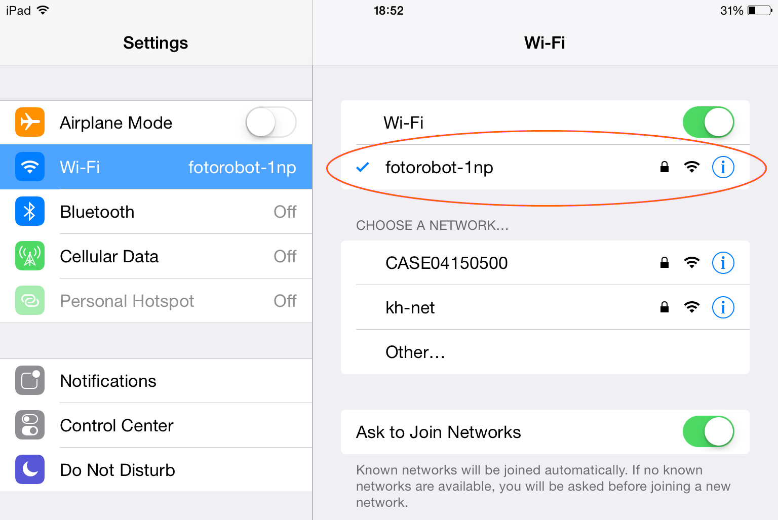
- Connect your device to the same wireless network which connects to the CASE.
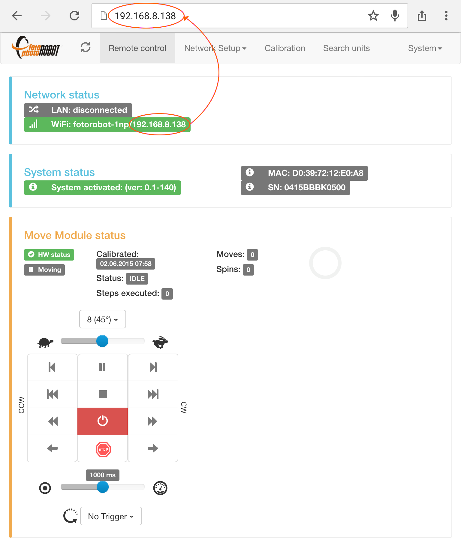
- Now, the CASE is connected to your selected wireless network and you can access it via its IP address shown in the Network status field.
4.3.2. PhotoRobot Controls App
In late 2015, PhotoRobot launched its controlling app, PhotoRobot Controls. PhotoRobot Controls provides controls over the robots, cameras and strobes; edits the photographs in real time during the sequence; renders special techniques such as automated cut-out; chromakey masking and DoF stacking for enhanced depth of field; with workflow, database, automated upload, and much more.
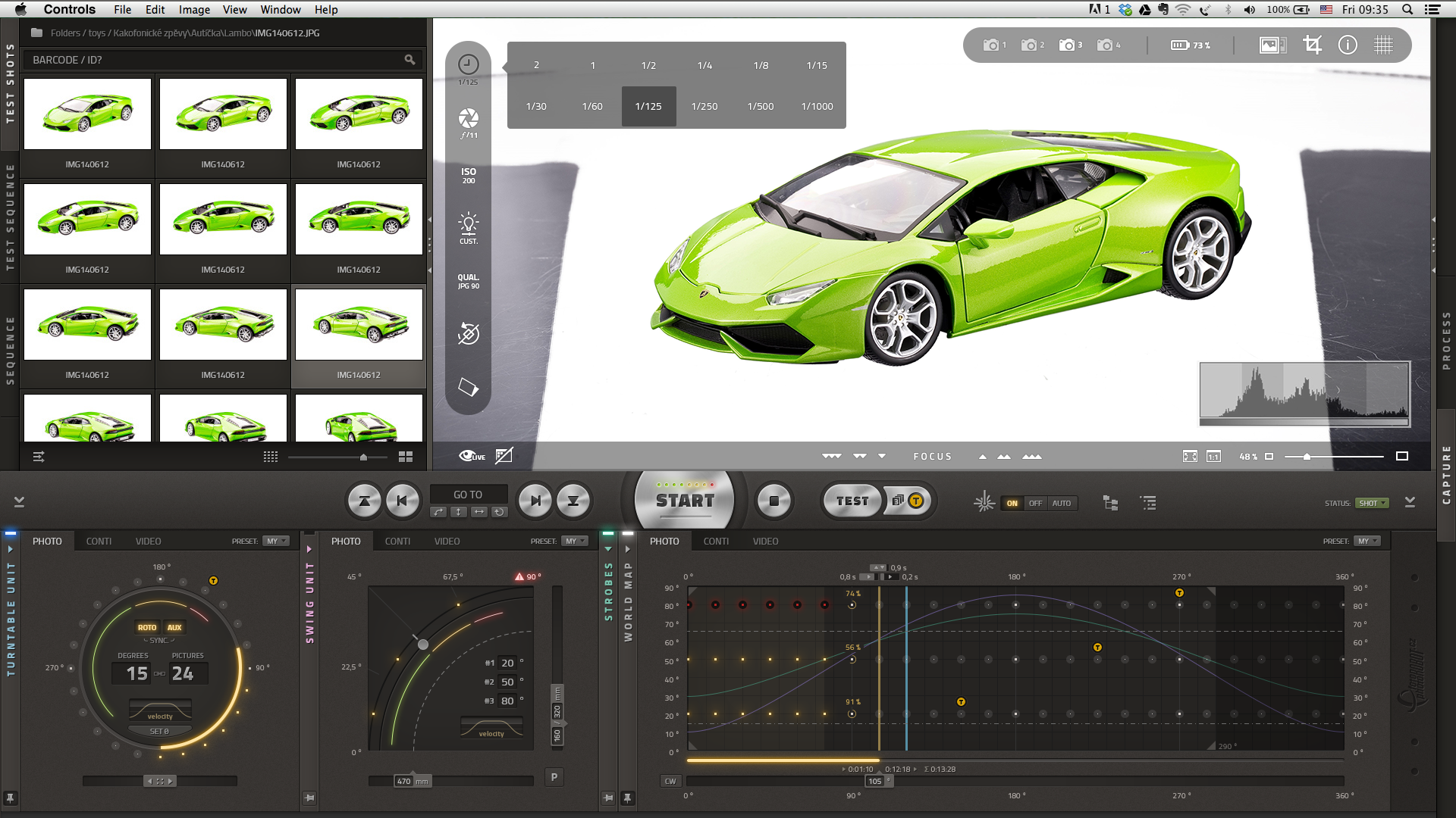
- The PhotoRobot Controls application user interface is both visual and intuitive to use.
4.4. Calibrate
Note: The latest generation of the CASE 850 no longer uses the magnetic suction cup. Instead, a hidden optical sensor reads the full 360° rotation from a mechanical bevel ground into the edge of the glass plate. Calibration works exactly the same — there is simply no suction cup to fit, so you can skip the suction-cup steps below.
Calibration is important for the CASE’s precision and optimal performance, and must be completed after each CASE installation. Further, calibration is advisable according to specific conditions, the volume of photographs taken; aging of the X-rings, cleanliness of the glass plate, weight of the photographed products, etc.
To calibrate the CASE, you must connect it to the Browser-based User Interface application (see chapter 4.3.1 - Web-based User Interface App).
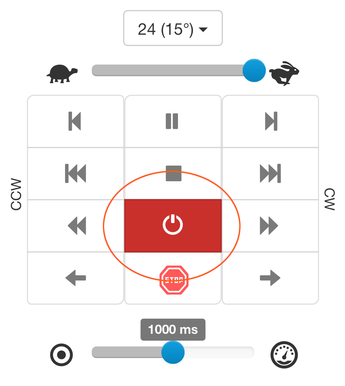
- Before you begin the calibration, make sure the CASE is turned on and that there is no power to the motors so that you can rotate the glass plate freely by hand.
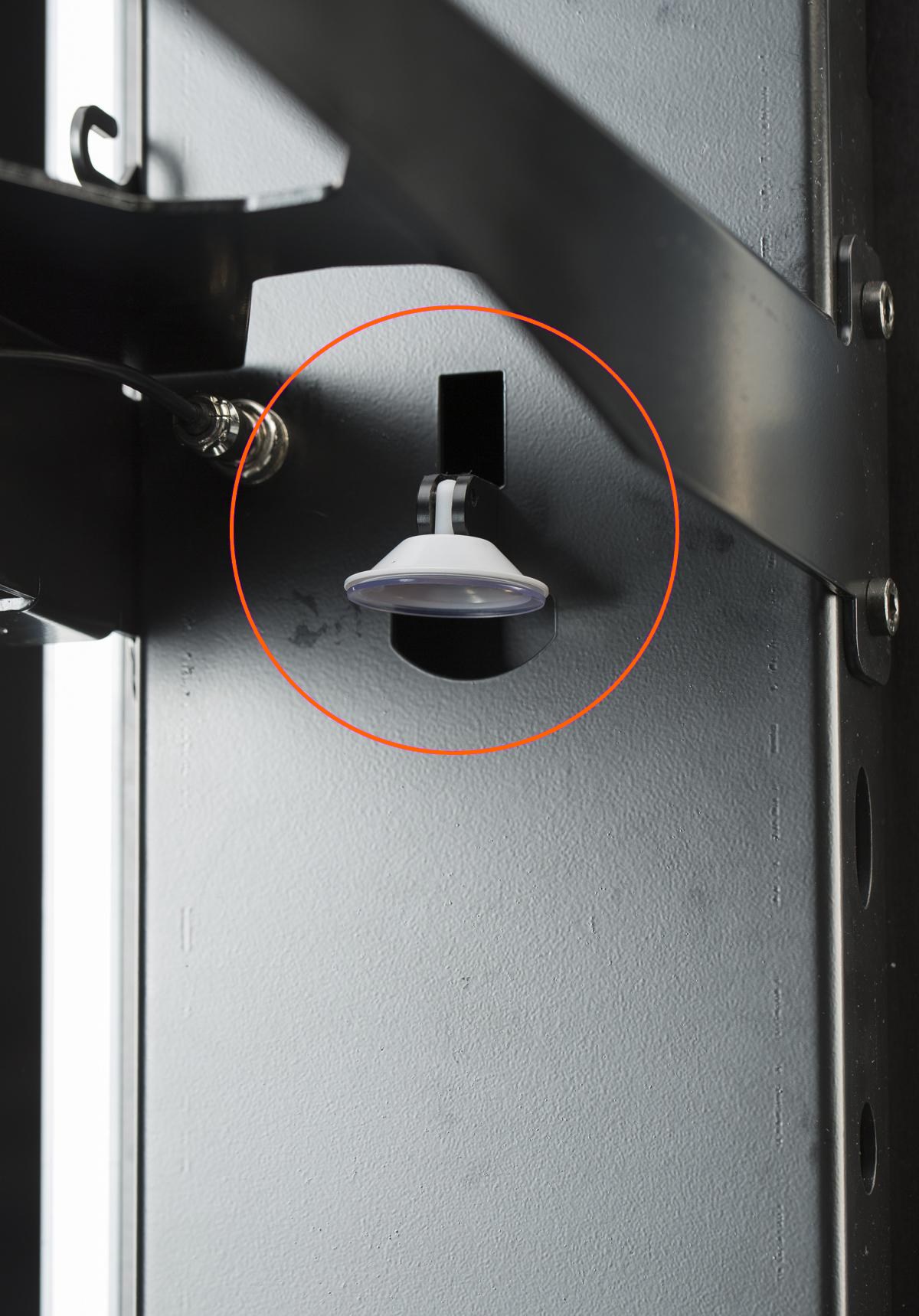
- For calibration, you need a magnetic suction cup which is kept in the inner side of the CASE’s body.
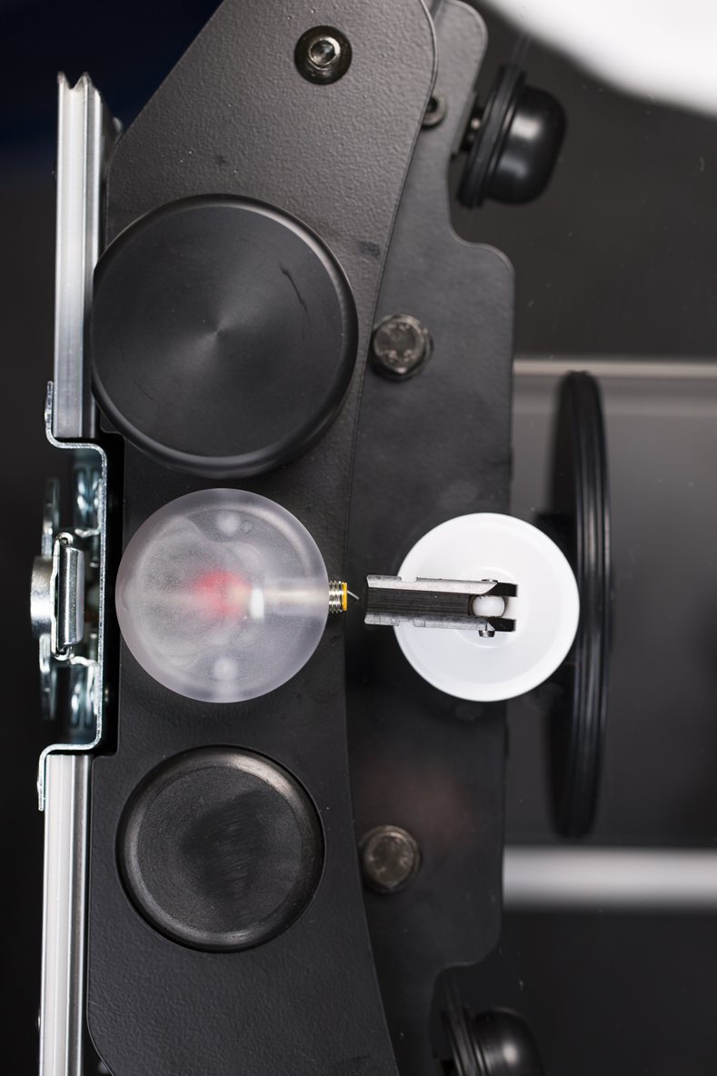
- The calibration probe is located on top of the CASE next to the encoder. Place the closed suction cup near the probe (prox. 0,5 mm or 0,02 inches). The correct positioning is indicated by the red light probe.

- Rotate the glass plate with the suction cup beside the probe. Open and close the suction cup – it should secure firmly to the glass plate.

- When you rotate the glass plate, the suction cup will meet the calibration probe. This will switch on the red light to indicate proper positioning of both parts.
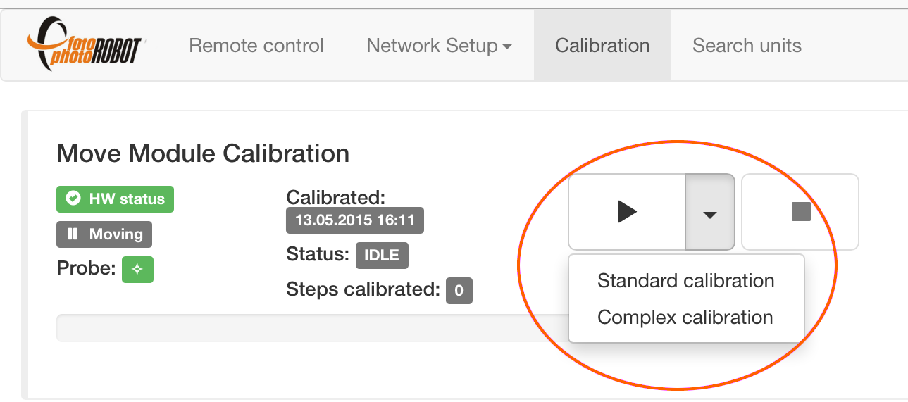
- In the Browser-based User Interface application, go to the Calibration Menu. Select Standard (fast and sufficient) or Complex (longer and more precise) calibration, hit the play button, and the automatic calibration sequence will begin.
4.5. Centering Laser (Dot Test)
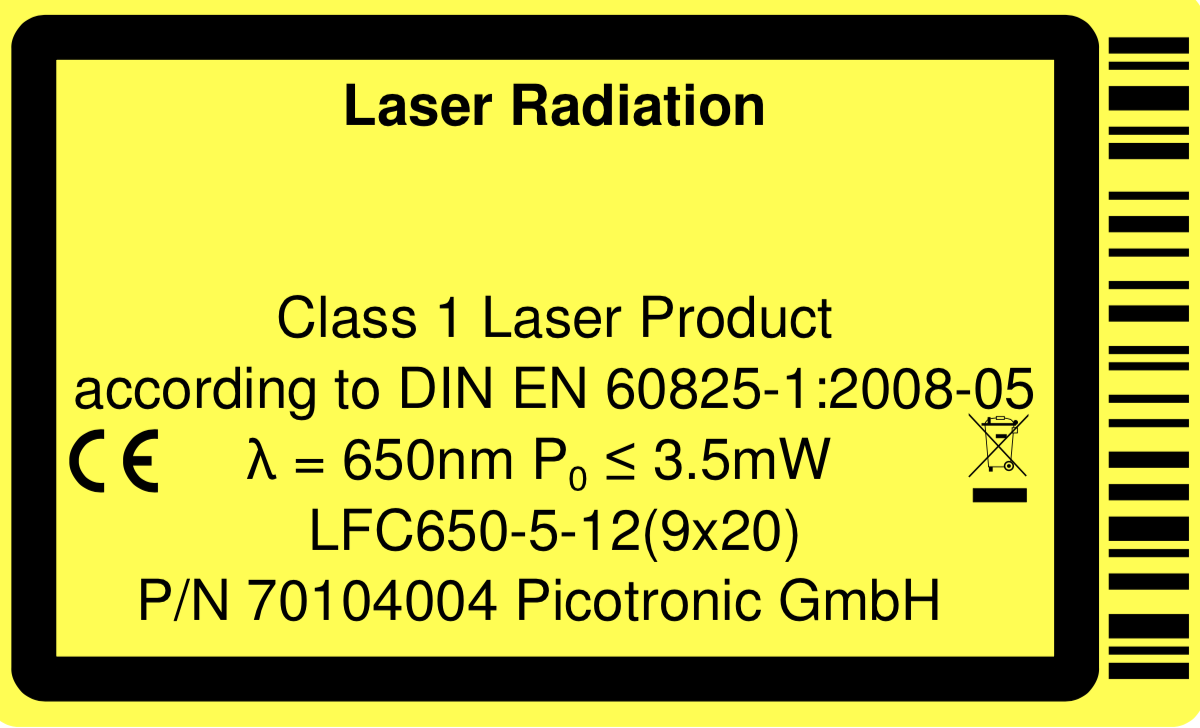
CAUTION: Laser Class 1 (λ = 650nm P0 ≤ 3.5mW) is used - avoid direct eye exposure (do not look into the beam) - and in addition - optionally - use protection Glasses or Goggles.
To be able to accurately place every photographed product on the glass plate, it is vitally important to precisely center the integrated cross laser. Fortunately, there is an easy and fun technique to do so, described below.
Note: The CASE 850 has a built-in cross laser. For projection from above or from other convenient angles, optional add-on lasers are available as accessories. The system drives them automatically — they switch on after each photo sequence so that the next product can be placed immediately, and switch off during capture so that the laser never appears in the photographs. Add-on lasers are best suited to permanent studio installations, while for mobile on-location work, the built-in laser alone is usually preferable.

- Fix the tape to the approximate center of the glass plate and run a sequence with a few stops (six in this example).
- Mark the laser crossing at each stop with a pen.
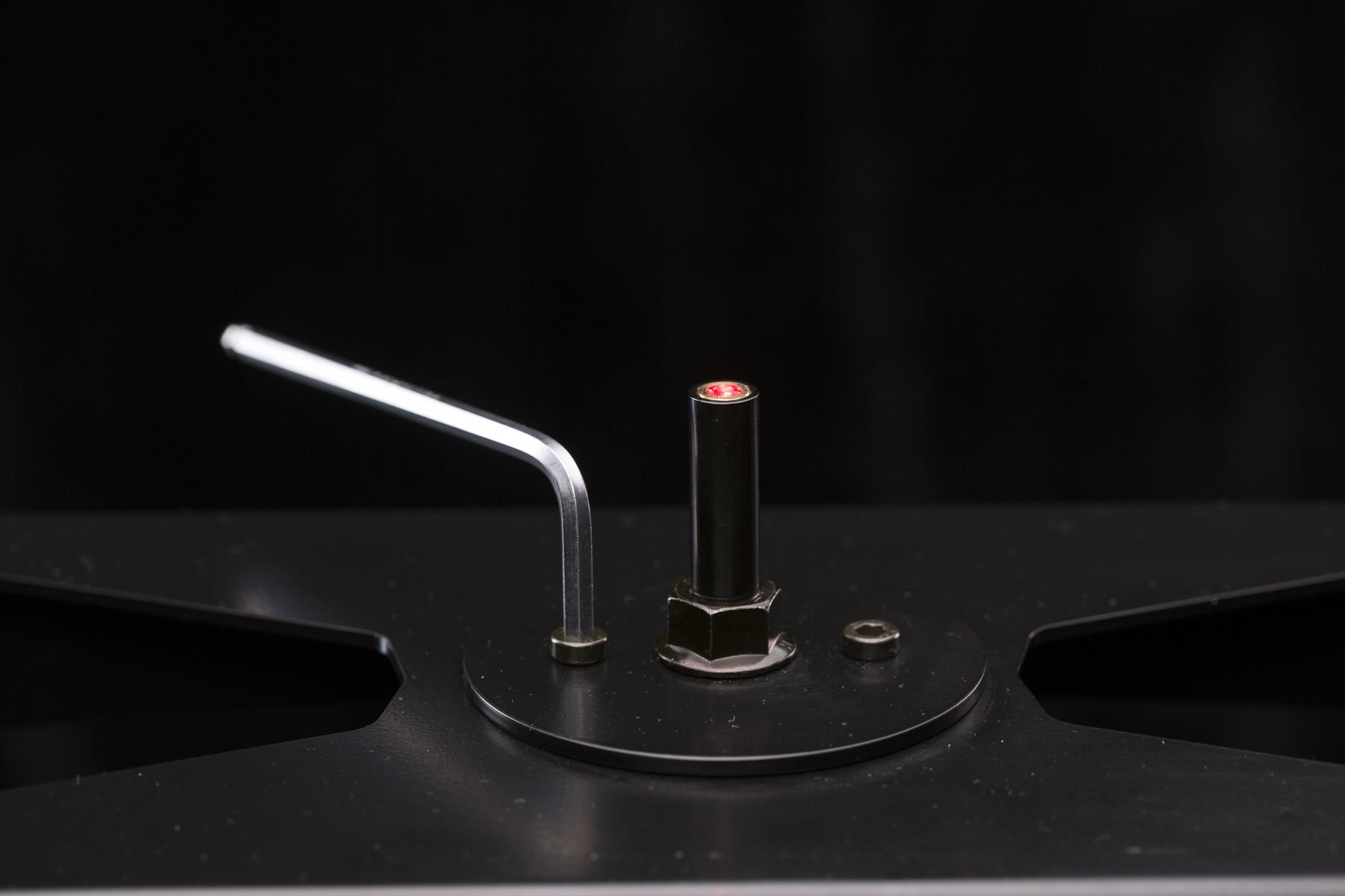
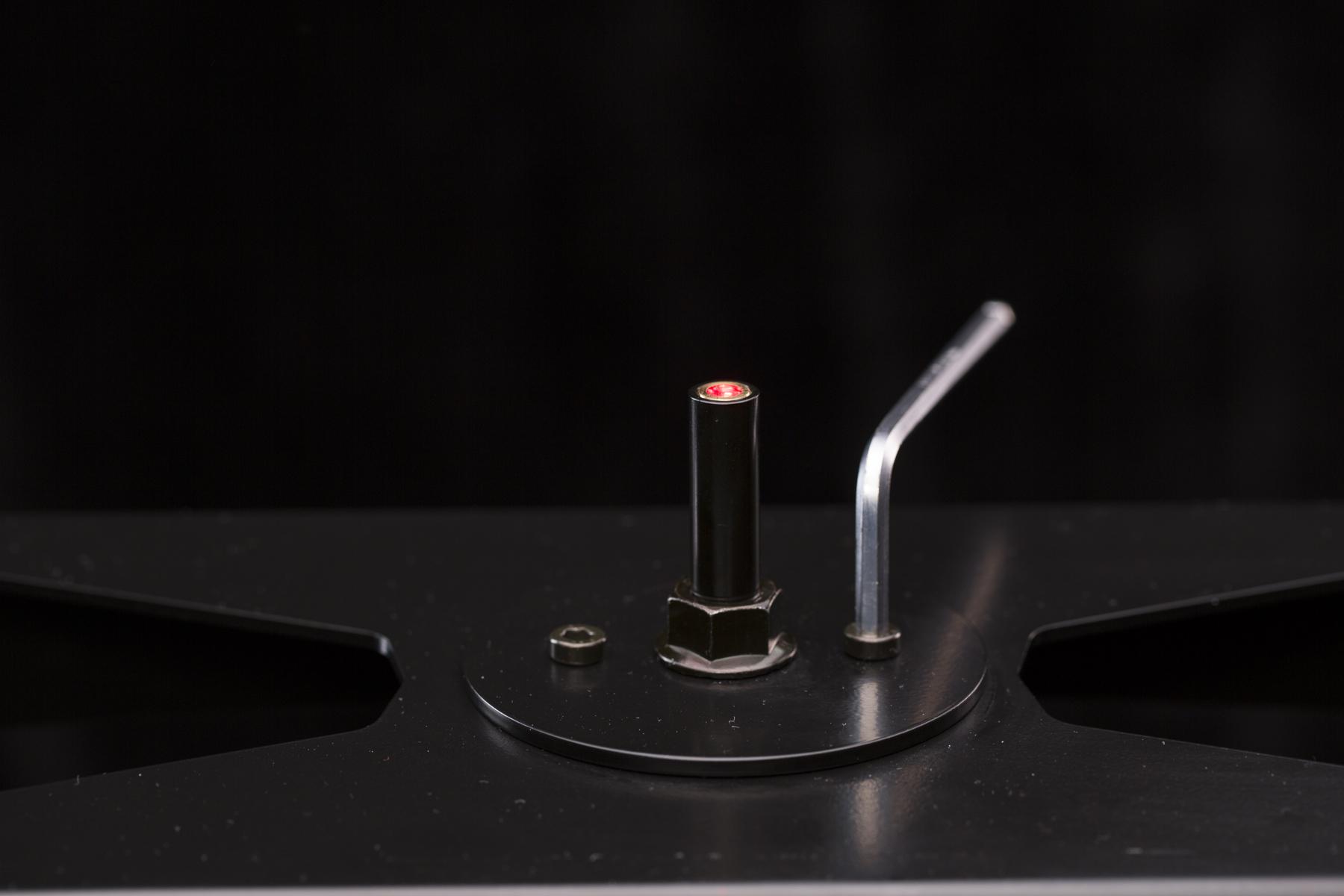
- Loosen the laser’s screws by the hex key so the laser can move freely.


- When as shown above, the laser can now move left - right, and forward - backward.

- Mark the laser crossing at each sequence stop using the instructions above.
- Link the opposite marks – this creates the exact centre / axis of the glass plate.
- Move the laser cross to the centre of the glass plate and tighten the laser’s screws.
4.6. Place the Product
It is important to place the product’s spin axis at the center of the glass plate. The exact center of roation (ECR) of the glass plate is depicted by the integrated cross laser (setting it properly is described in the previous chapter). However, to determine product’s spin axis, it might be rather tricky. Usually, it is the geometrical center, but there are exceptions; e.g. the long handled pan should have a spin axis in the geometrical center of the pan, while the long handle should rotate around it.
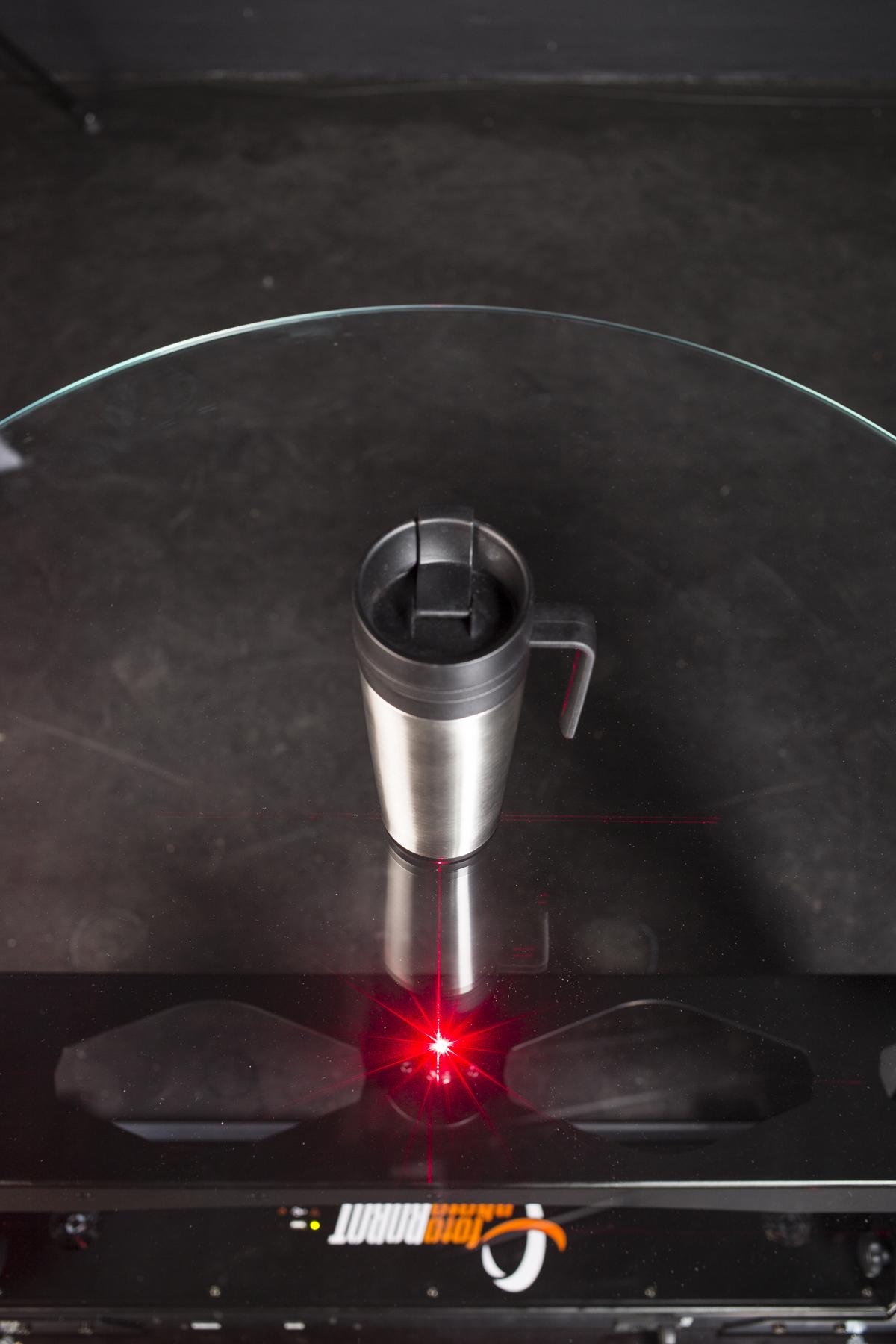
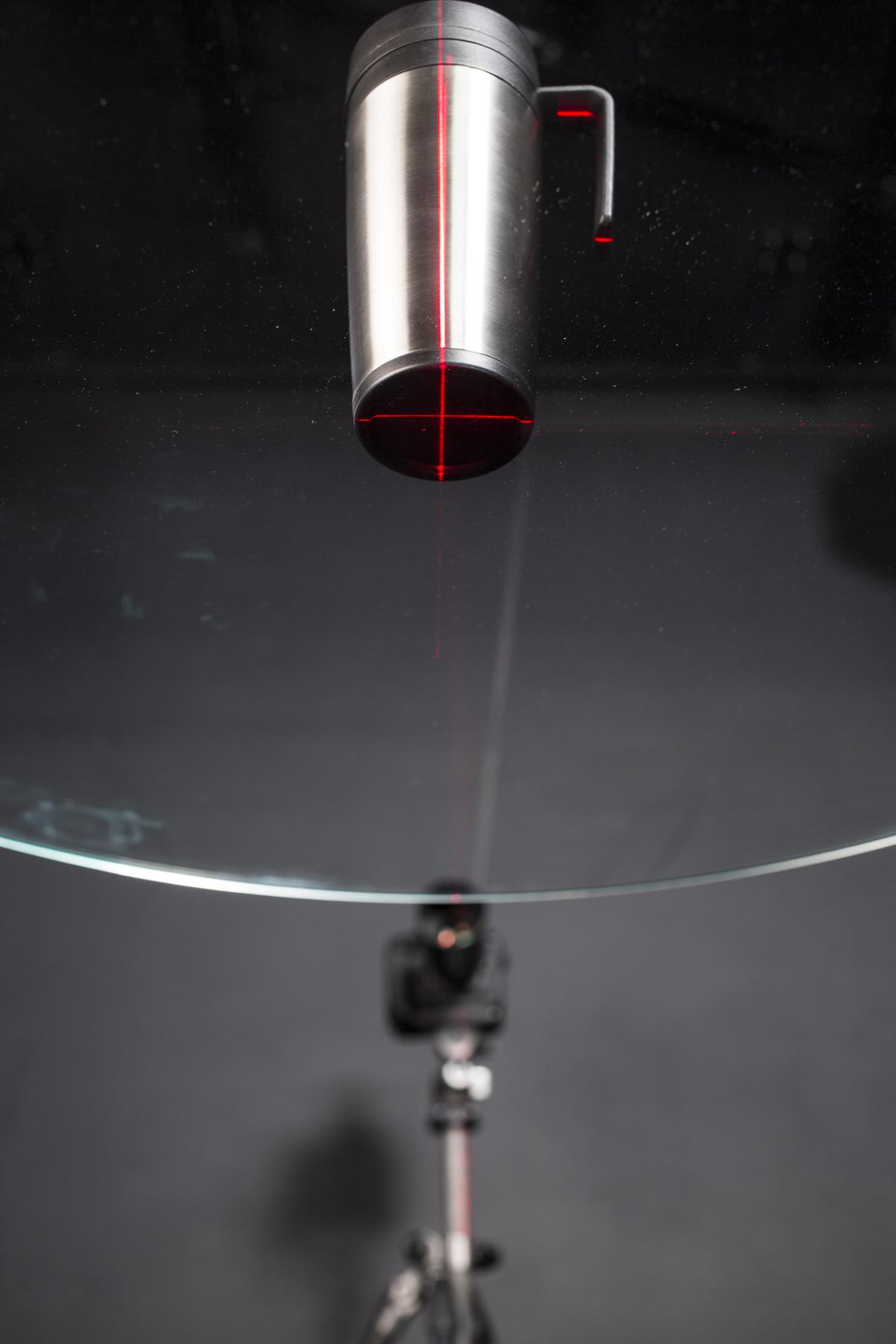
- With the laser cross projecting from the bottom, it is usually easier to determine the product’s axis from below.
CAUTION: It is not allowed to place sharp objects onto hardened glass plate! It may scratch or break the glass. The weight capacity or the table may be limited if weight is not distributed evenly or focused on several points only. To place sharp objects on the table, it is recommended to use transparent acrylic glass as a separation layer to the glass-table surface.
4.7. Set the Camera
4.7.1. Place the Camera
Correct positioning of the camera is vital when shooting 360 degree photographs; it is necessary for the product to rotate smoothly in the middle of the frame.
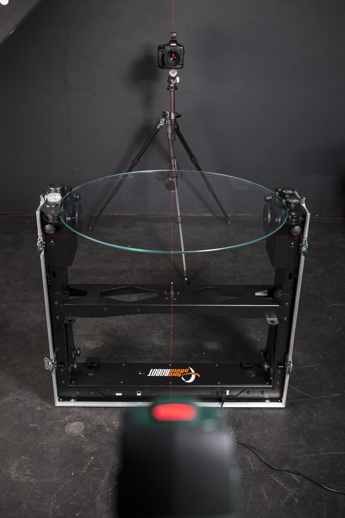
- Use the self-leveling laser to precisely align the camera and the CASE. Project the self-leveling laser in line with the integrated cross laser and place the camera so the laser runs through the lenses’ center.
4.7.2. Connect the Camera
If you are using the PhotoRobot desktop app (PhotoRobot Controls) to operate the CASE, you can likewise use it to control the camera. That, or you can simply synchronize the camera with the robot by wireless or cable trigger plugged directly to the CASE.
4.7.3. Camera Settings
Naturally, it is necessary to set the camera’s focus, exposure, and image quality. To do this, we recommend the following.
- Use JPEG for standard production – the in-camera processing of the Canon body (or iPhone) delivers excellent, ready-to-use results; RAW remains an option for enthusiasts who want to fine-tune maximum dynamic range, e.g. for the heavy backlight of a pure white background.
- Use low ISO – you will get the highest dynamic range and image quality from your sensor.
- Use LiveView – it is the best way to focus and align your subject properly.
- Test your lens – detect your lenses’ optimal performance; you are looking for the highest aperture value with acceptable sharpness and contrast transmission – most lenses drop image quality at about f/16.
4.8. Set the Light
Setting the light properly is the most difficult of all tasks when shooting 360 degree photographs. We recommend using strobes, as they allowfor more freedom in terms of light modeling, and also save you time by enabling faster shutter speeds.
4.8.1. Place the Lights
It is very important to light the background evenly to get a pure white background without requiring any post-processing. You will need one or two lights to do so, depending on the product size (small products do not require as much evenly lit space as large products).
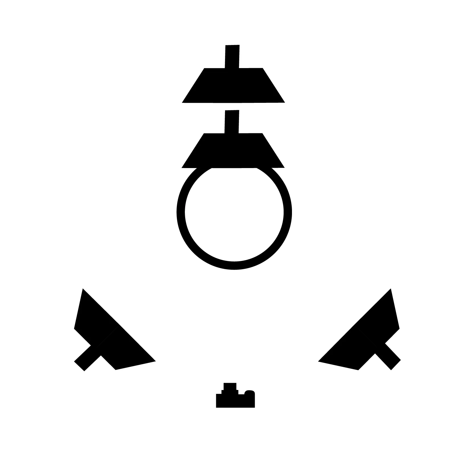
- Top View is illustrated above – with one or two strobes in the back, and two strobes in the front / side.
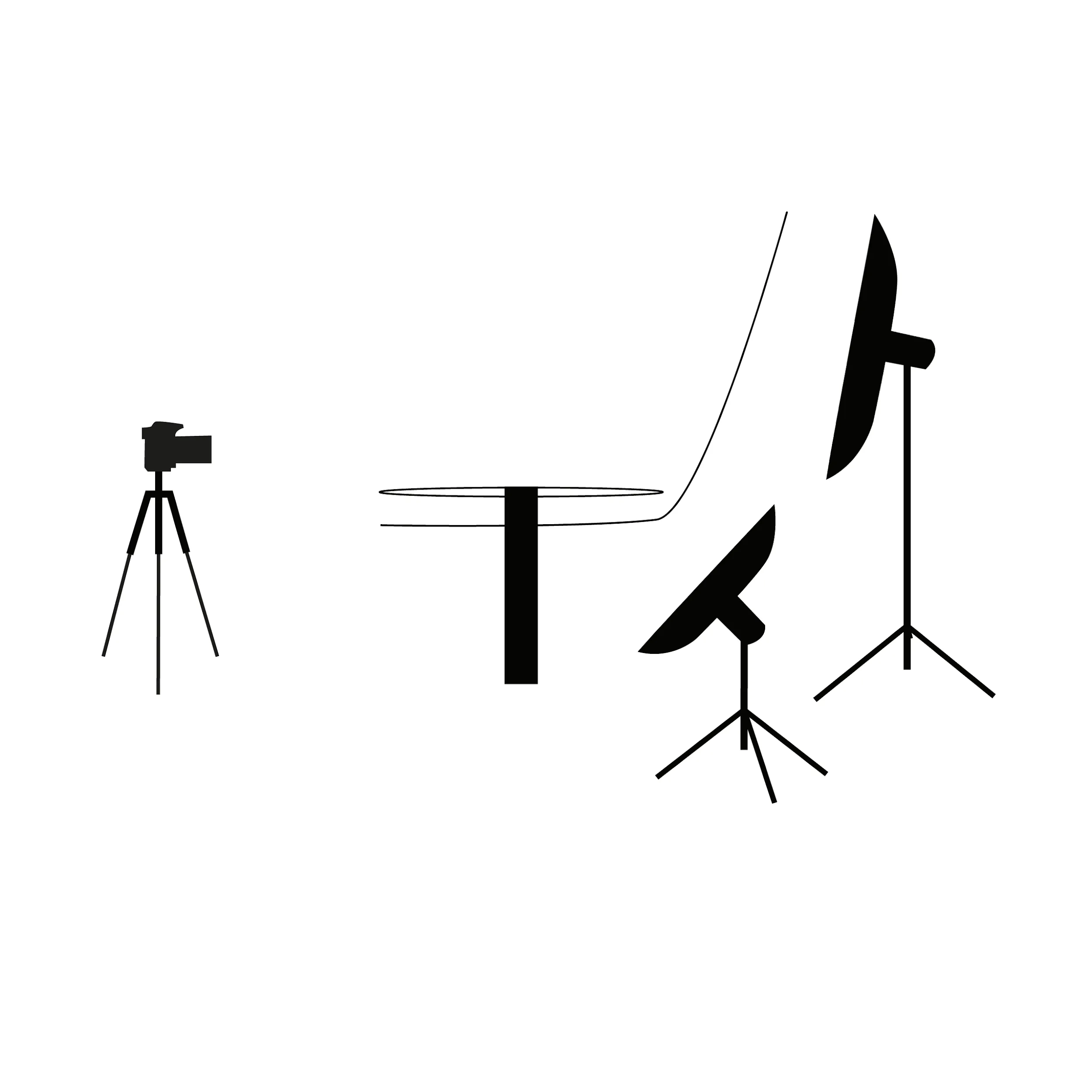
- Side View is illustrated above – with placement of the back strobes.
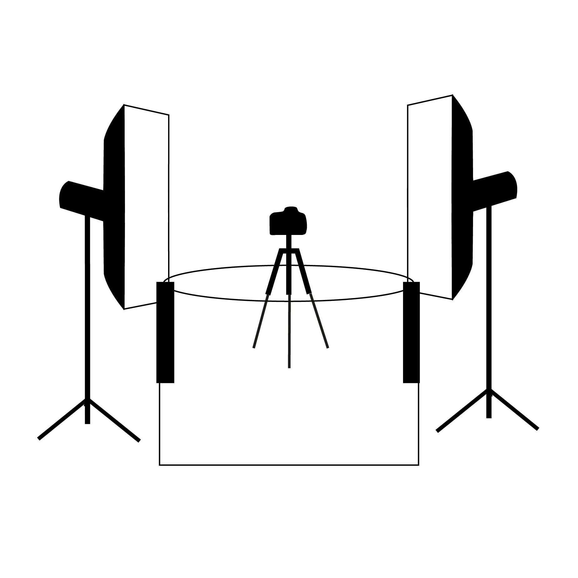
- This is the Back to Front View – with two strobes at the front / side.
The rest of the lighting is open to your creative interpretation. Keep in mind, lighting for 360 degree photography is vastly different to lighting a single still shot; the product reflects the lighting variously at each angle, e.g. 36 angles. This usually disqualifies any use of hard lighting.
4.8.2. Connect the Lights
If you use the PhotoRobot desktop app (PhotoRobot Controls) to operate the CASE, you can use it to comfortably control all the settings of the strobes (FOMEI / RiME LITE, Broncolor, Profoto, and others including manufacturers with support upcoming in the near future). Synchronization of the camera shutter to the strobes during the spin sequence needs to be performed by a standard sync cord or remote trigger.
4.8.3. Lights Settings
Intensity of the lighting needs to be set to comply with the designated aperture value (to get optimum depth of field and optical quality). To do this, use the following tips.
- Use sufficiently powerful strobes – around 700 Ws works well today; for the most even illumination of both the product and the background, we recommend using several lights to achieve finer control over the lighting. Adequate power also shortens recycling times and prolongs strobe lifespan.
- Use beauty dishes and strip softboxes – they provide soft yet efficient modeling light; perfect for 360 degree photography.
- Get close to the product – leaving the strobes far from the product degrades light quality.
- Avoid flat lighting – it is very rarely flattering on the product, and does not properly depict the product's material.
4.9. Run the Sequence
Consider the following when setting the sequence up:
- Number of steps – the more images in a spin, the smoother the transition will be between the frames of 360 degree experience, but also longer production time and larger data volume. 24 - 36 shots a spin is optimal in most cases (read more in 360 Product Photography - ContentFormats and Production).
- Acceleration and speed – velocity needs to comply with the characteristics of the photographed product, e.g. slow movement to avoid swinging of the product supported by the fishing line.
- Delay before / after shots – delays are sometimes necessary to settle the swinging product or to give strobes time to fully charge.
The following illustrations use the Browser-based User Interface App to run the sequence. For instructions on how to connect the CASE to this app, please refer to chapter 4.3.1 - Web-based User Interface App.
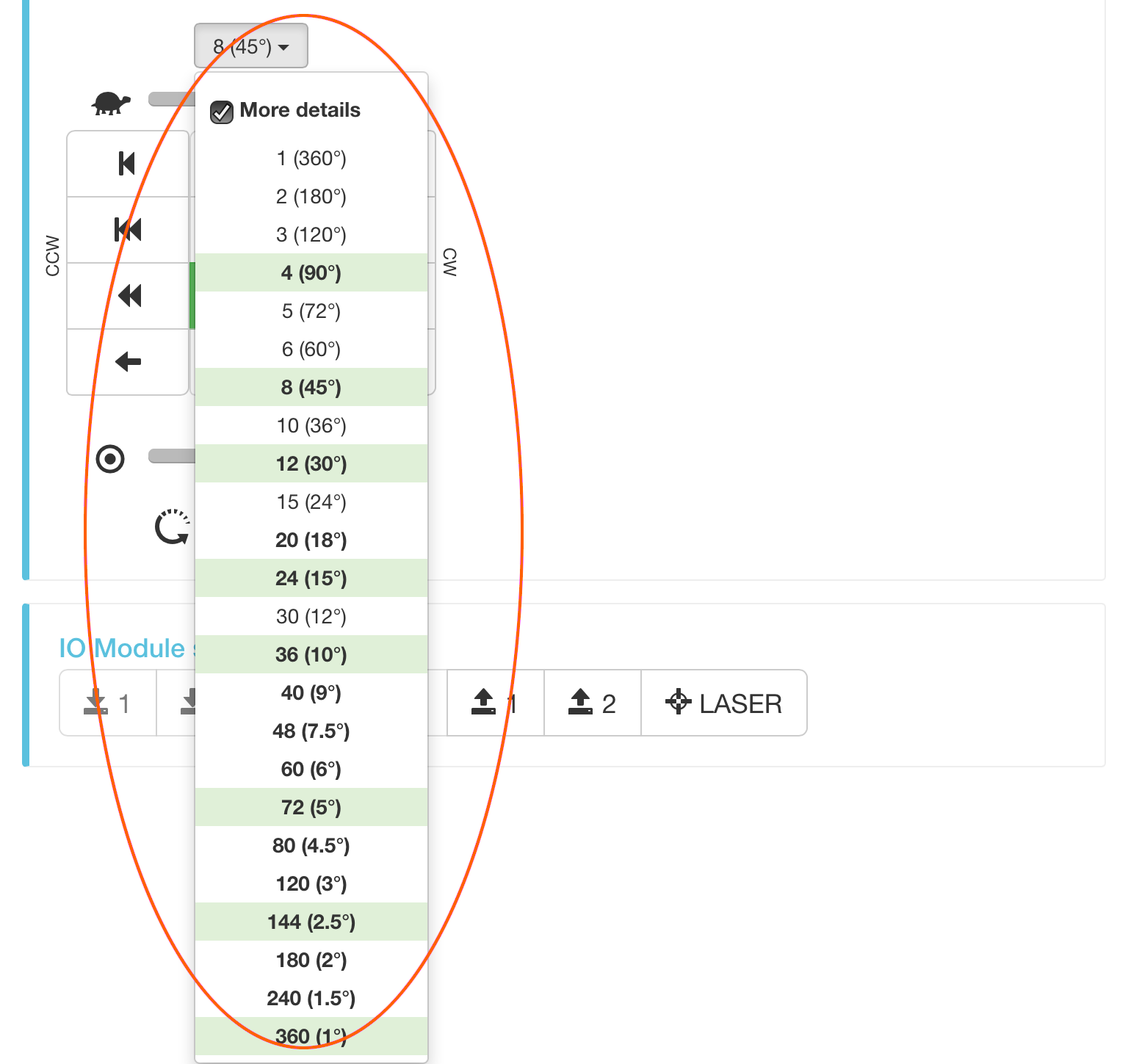
- You can select from the wide range of preset sequences.
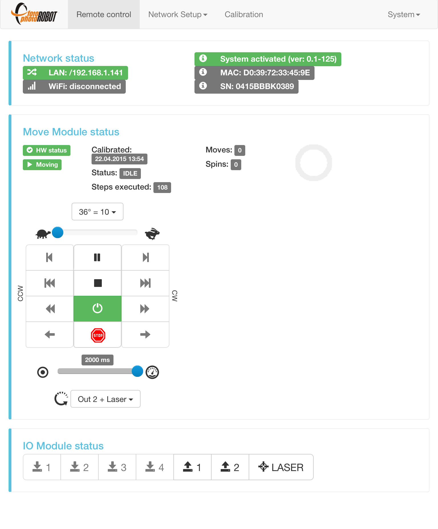
- The CASE is operated by the circled controller.
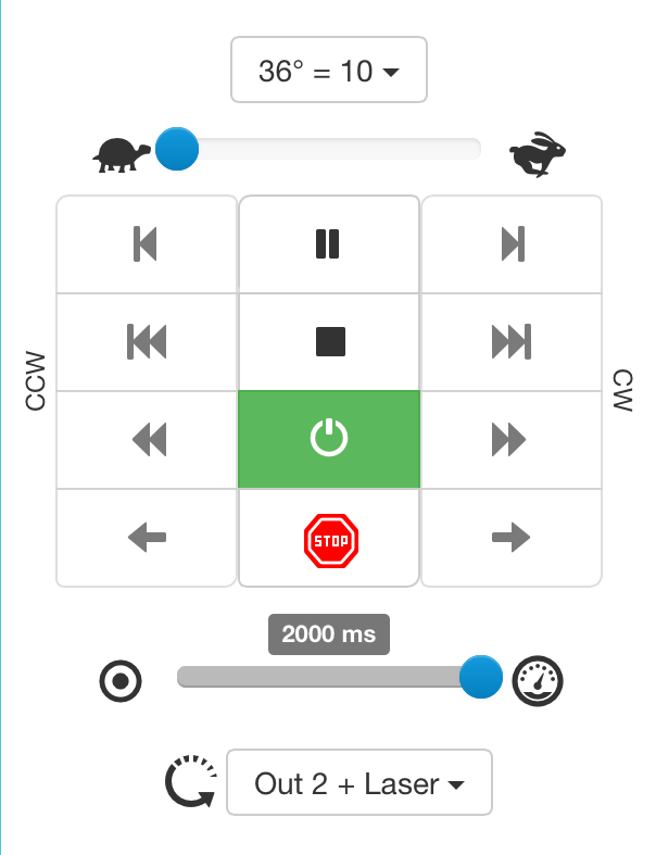
- Preset sequences
- Min / Max rotation speed
- One counterclockwise (CCW) / one clockwise (CW) step
- 360° CCW / CW steps mode
- Continuous CCW / CW steps mode
- Continuous CCW / CW rotation (no steps)
- Pause the rotation / sequence (will reach nearest stop)
- Stop the rotation / sequence (will immediately slow down and stop, but not reach nearest stop)
- Power / Deactivate the motors
- Immediate emergency stop (no slow-down ramp)
- Delay between sequence stops (camera trigger pressed in ½ of selected interval)
- Sequence pre-set (camera trigger pressed at each stop, laser lit when sequence not running)
5. Creating Outputs
The CASE 850 is operated by PhotoRobot Controls, our own software package that drives the camera, lights, and robot in a single workflow. In most cases, PhotoRobot Controls produces web-ready outputs directly — static images, deep-zoom 360° spin photography, videos and 3D models — with no third-party software required.
If you prefer your own pipeline, the images captured with the CASE 850 can be exported and processed in third-party tools of your choice. Alternatively, an API license is available for direct control of the CASE 850 hardware, letting you build custom software that performs the same tasks as PhotoRobot Controls.
6. Maintenance
To maintain optimal performance of the CASE 850, there is not much to do. See the following chapters describing good care of your device.
6.1. Cleaning
It is advisable to keep the CASE in clean environment, and to clean it regularly to prevent pollution of the electronics situated at the CASE’s base.
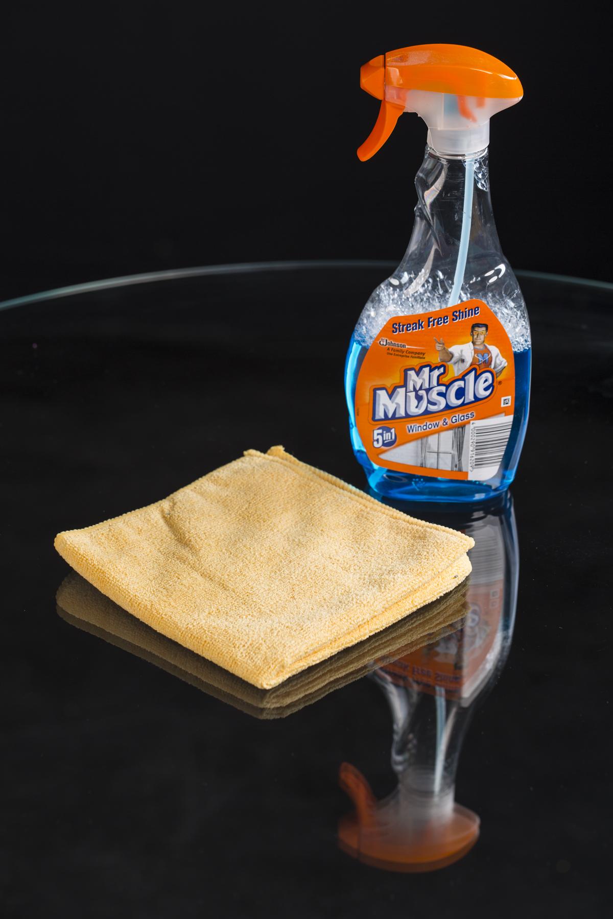
Note: Regular polishing of the glass is crucial. Any screen or window cleaner will work for this. Just make sure to use a towel or wipe that does not shed lint, fibers, fuzz, or other tiny particles.
6.2. Replacing X-rings
X-rings are used to provide grip for wheels that set the glass plate in motion or keep it in the correct position. Occasionally, however, they can wear out. This nothing to be alarmed by, though. You can purchase spare X-rings from PhotoRobot, or at your local hardware store. Then, replacing the X-rings is not difficult. See the instructions below.
The following sizes of X-rings are used in the CASE:
- NBR70 107.32 mm × 5.33 mm (2 pcs used for stepper motor wheel)
- NBR70 29,75 mm × 3,53 mm (4 pcs used for bottom support wheels)
- NBR70 33 mm × 2,62 mm (4 pcs used for side support wheels)
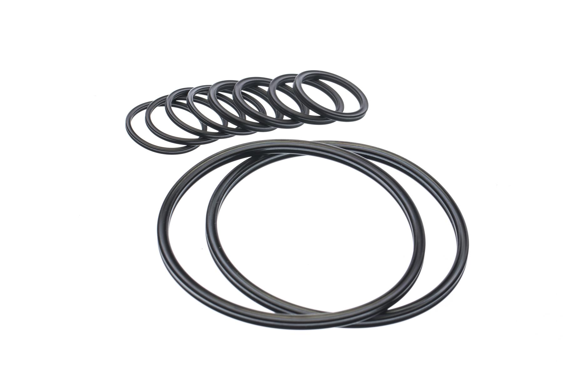
- The three sizes of spare X-rings used with the CASE are shown above.
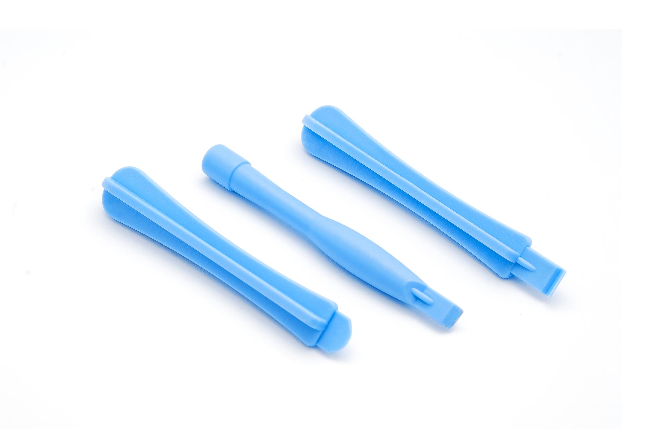
- It is advised to be as gentle as possible when replacing the X-rings. To avoid the risk of tearing still usable X-ring or damaging any of the CASE’s wheels, it is recommended to use a plastic pryer (opening tool) – pictured above. However, with extra caution, you may use a regular slotted screwdriver, as demonstrated by our experienced technician in the photographs below.
6.2.1. Stepper motor wheel
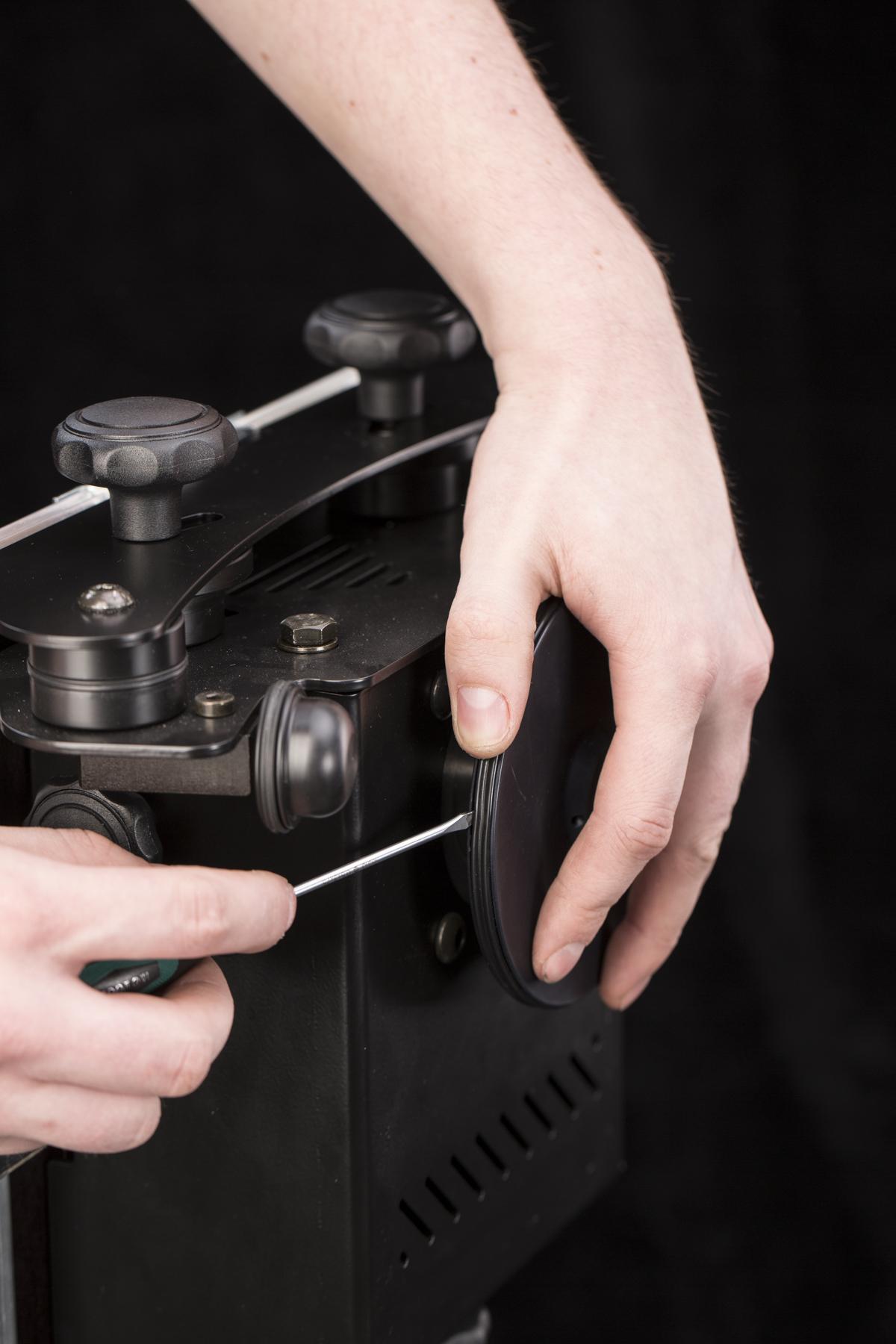
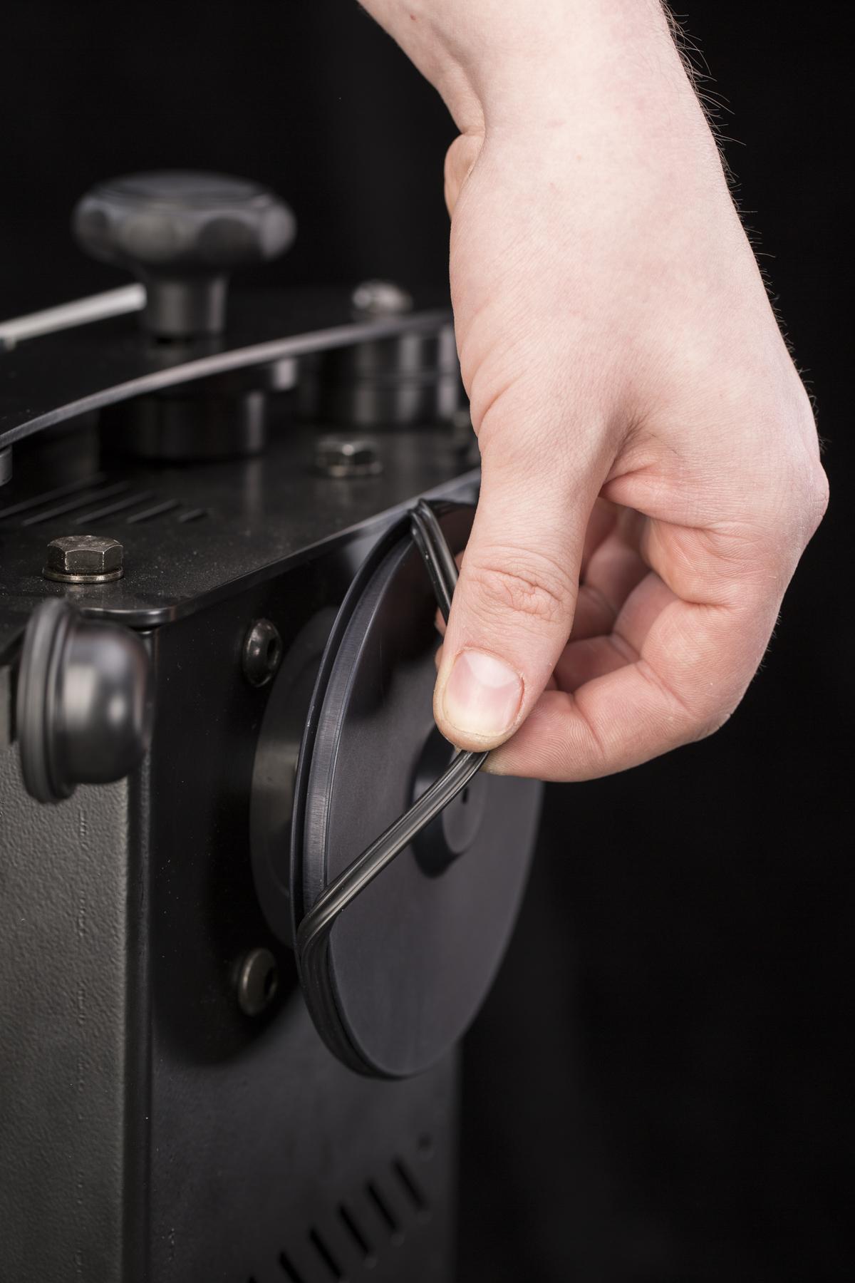
- The large X-ring fits to the stepper motor wheel that sets the glass plate in motion.
- Use the flat screwdriver to take the X-ring down.
- To mount the X-ring insert it to the wheel groove and pull it over the edge.
- Make sure the X-ring is not twisted.
- When the X-ring is properly mounted, knead it so the X-ring’s tension is the same throughout the wheel circumference.
6.2.2. Bottom support wheel
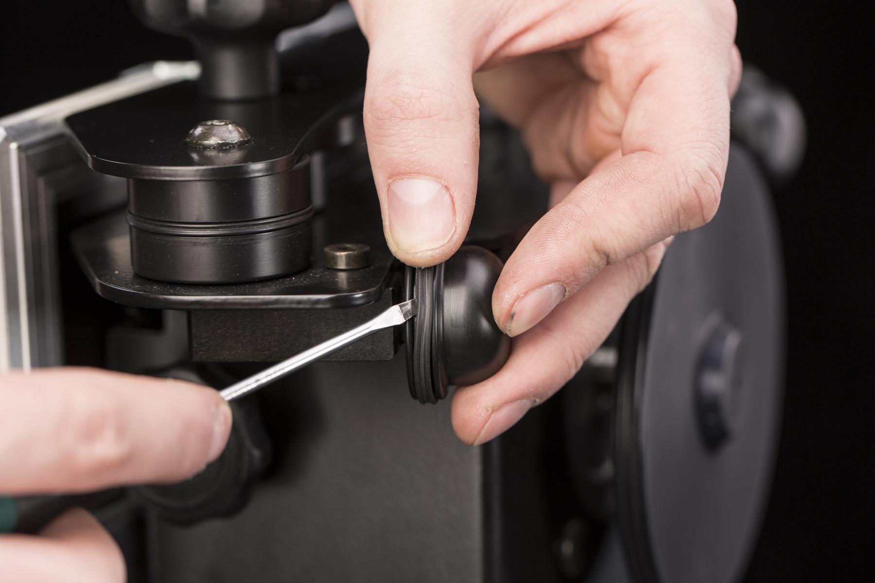
- The X-ring on the bottom support wheel can be replaced without dismounting the wheel.
6.2.3. Side support wheels
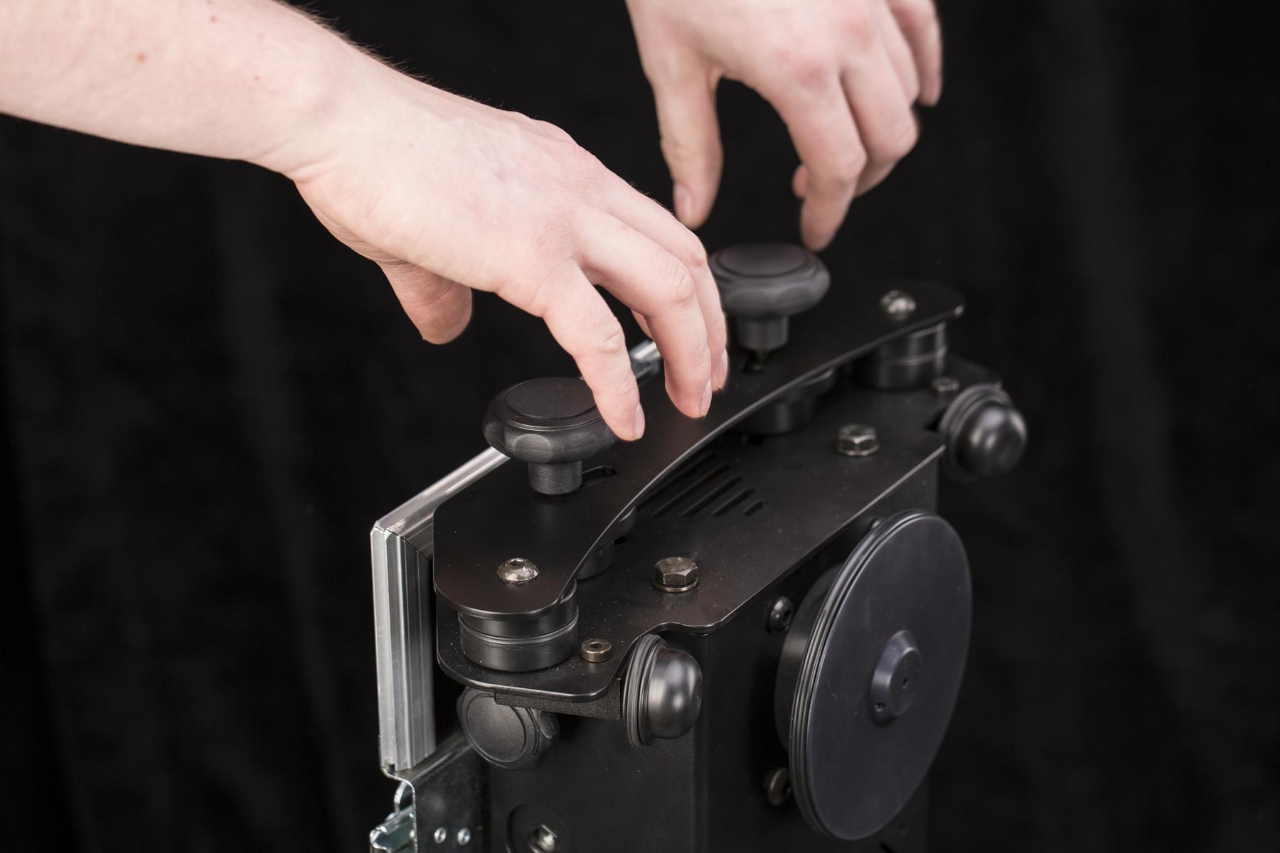
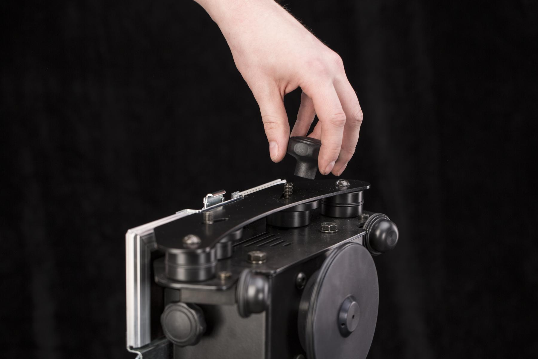
- To replace the X-rings on the side support wheels, you need to take off their cover.
- To take the cover off, there are two plastic nut lock handles to remove.
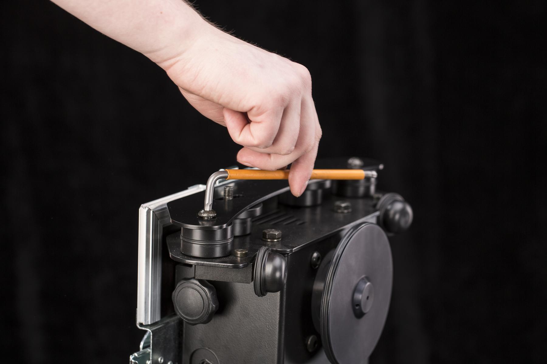
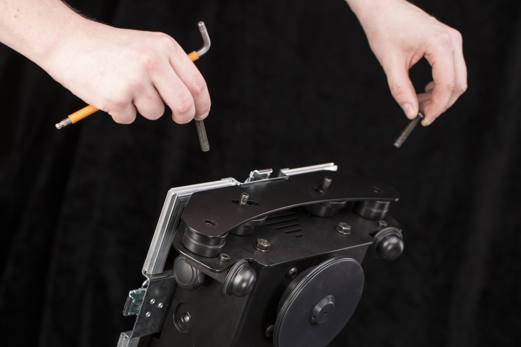
- Remove the hex screws going through the support wheels.
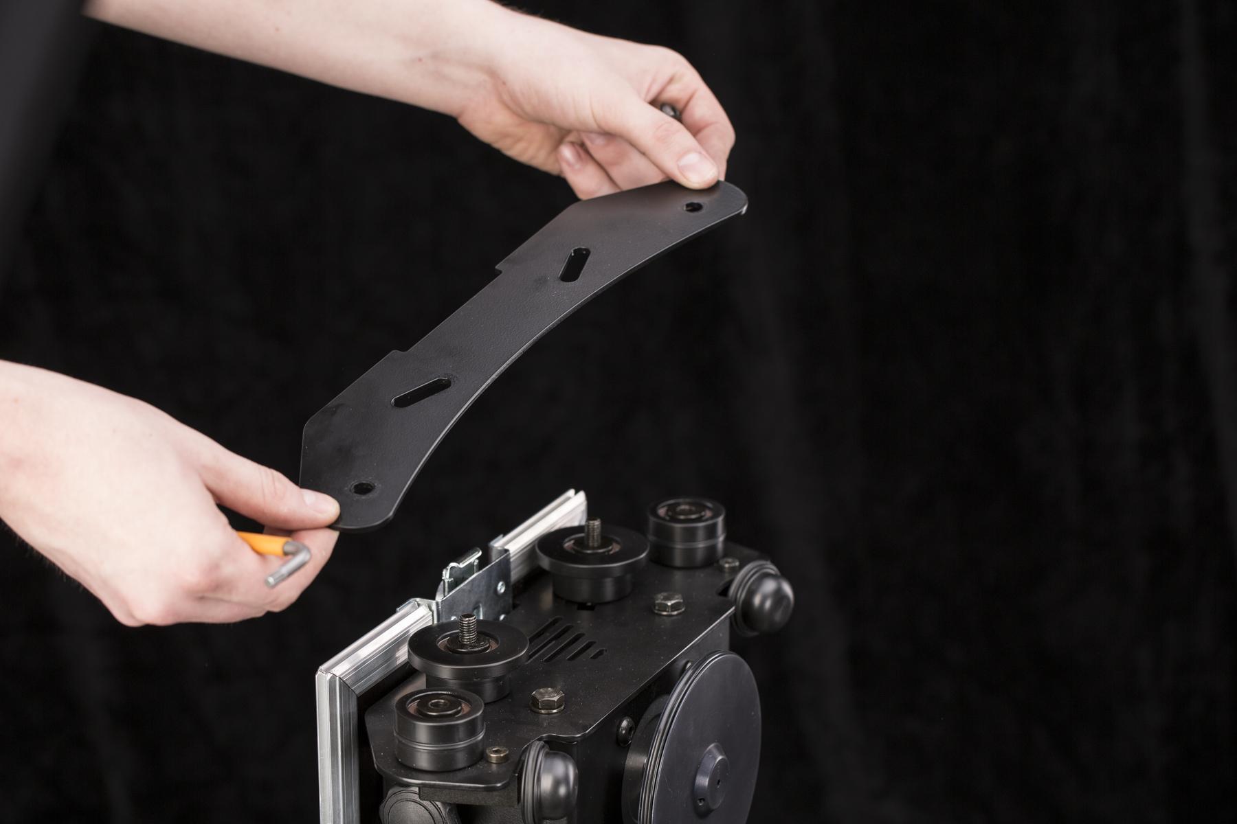
- Remove the cover of the support wheels.
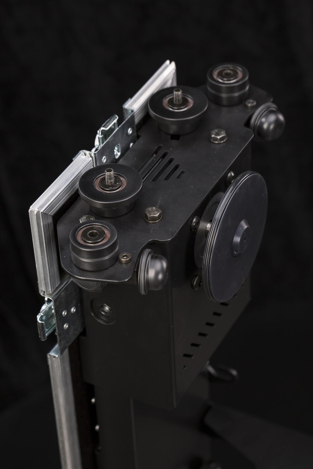
- The support wheels can now be fully taken out.
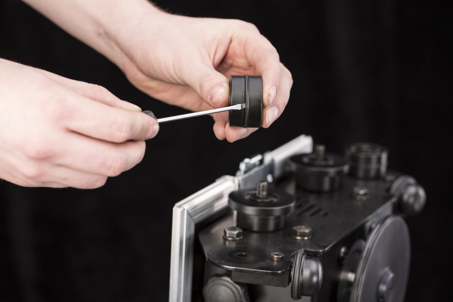
- Now, the X-ring can be easily replaced.
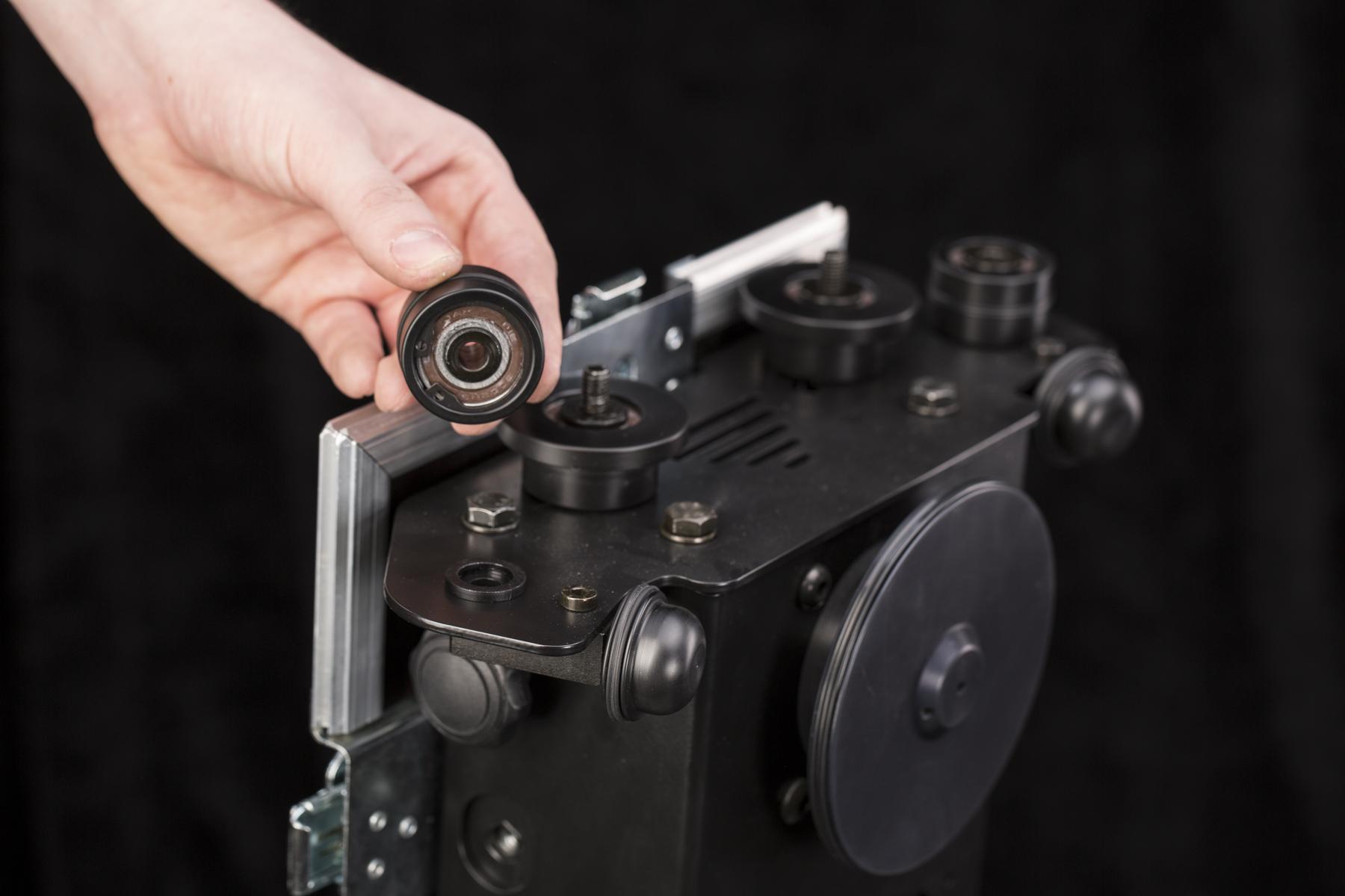
- When you take out the support wheel, the spacing washer can be left on the base. Be cautious not to drop and lose it.
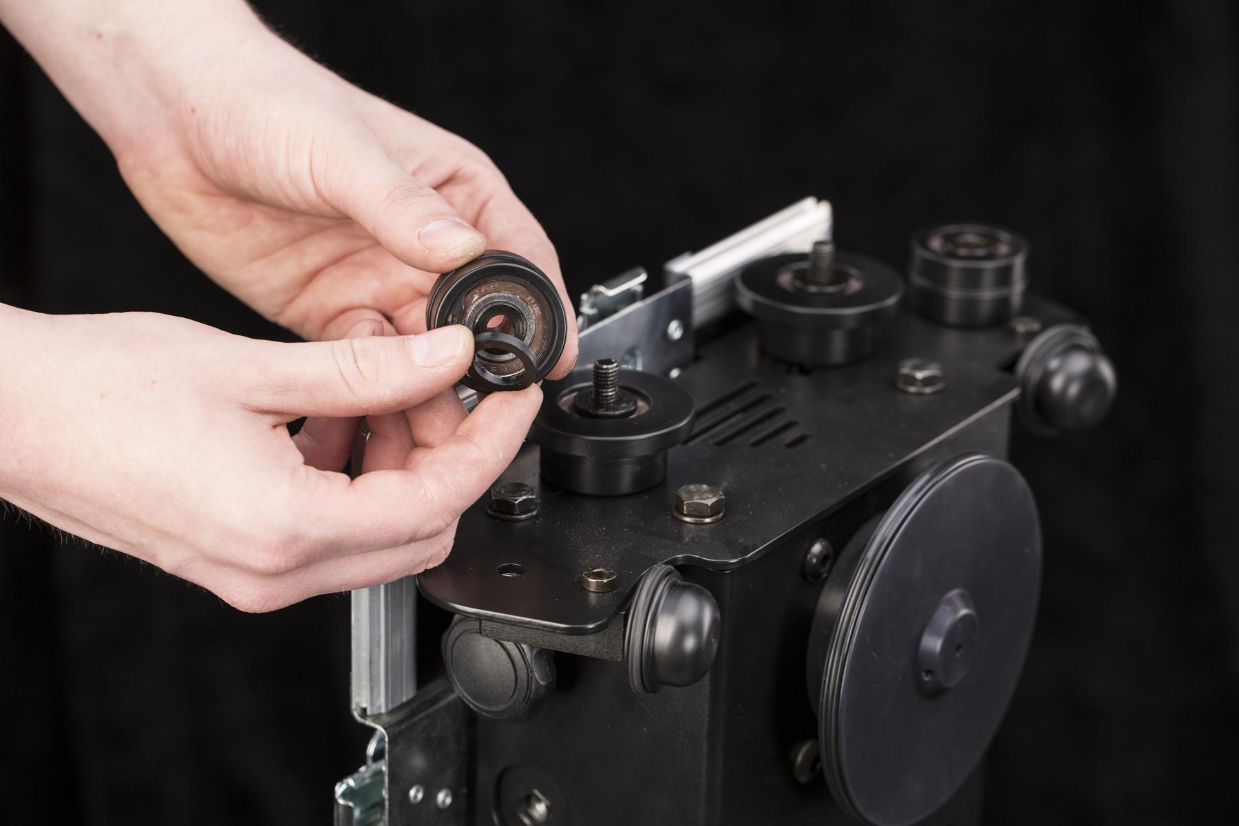
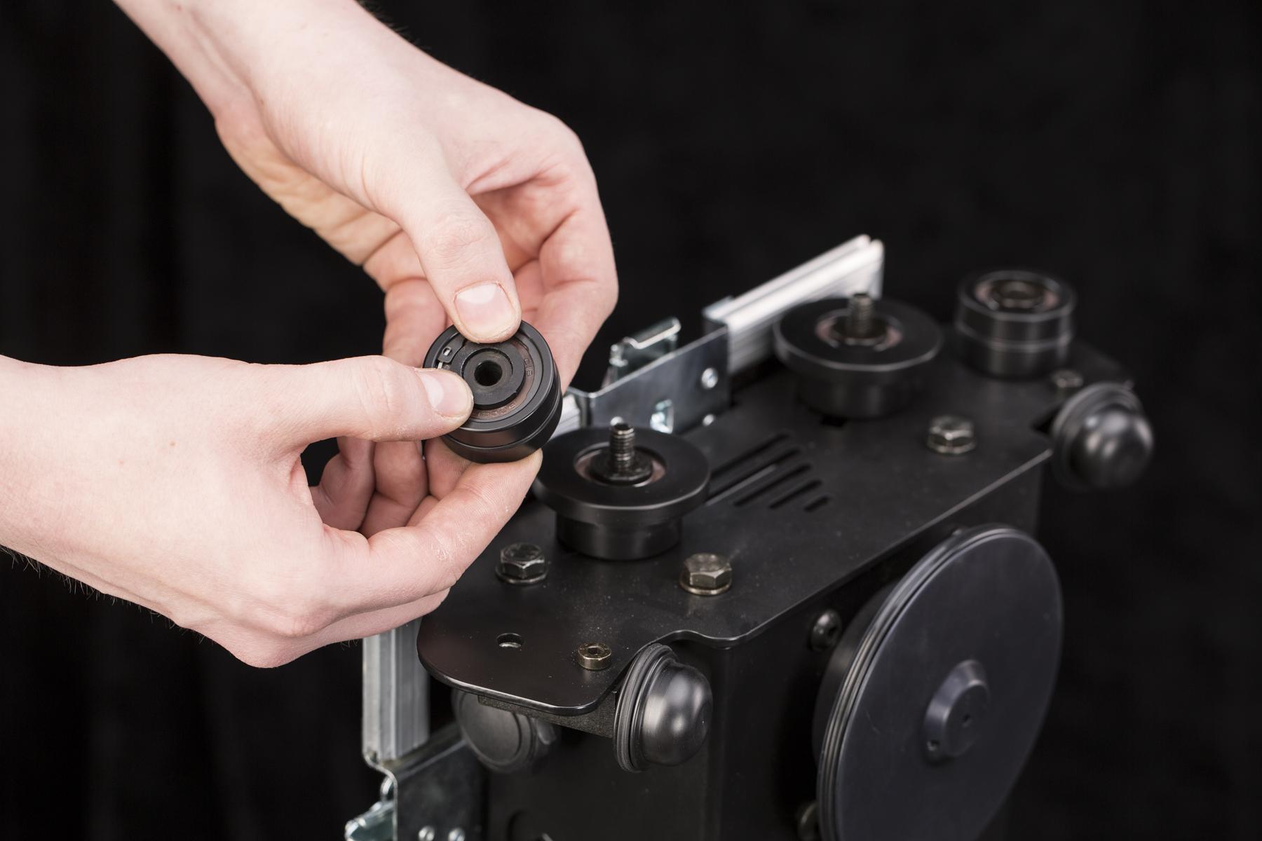
- Press the spacing washer back to the bottom of the support wheel and attach it back to the base.
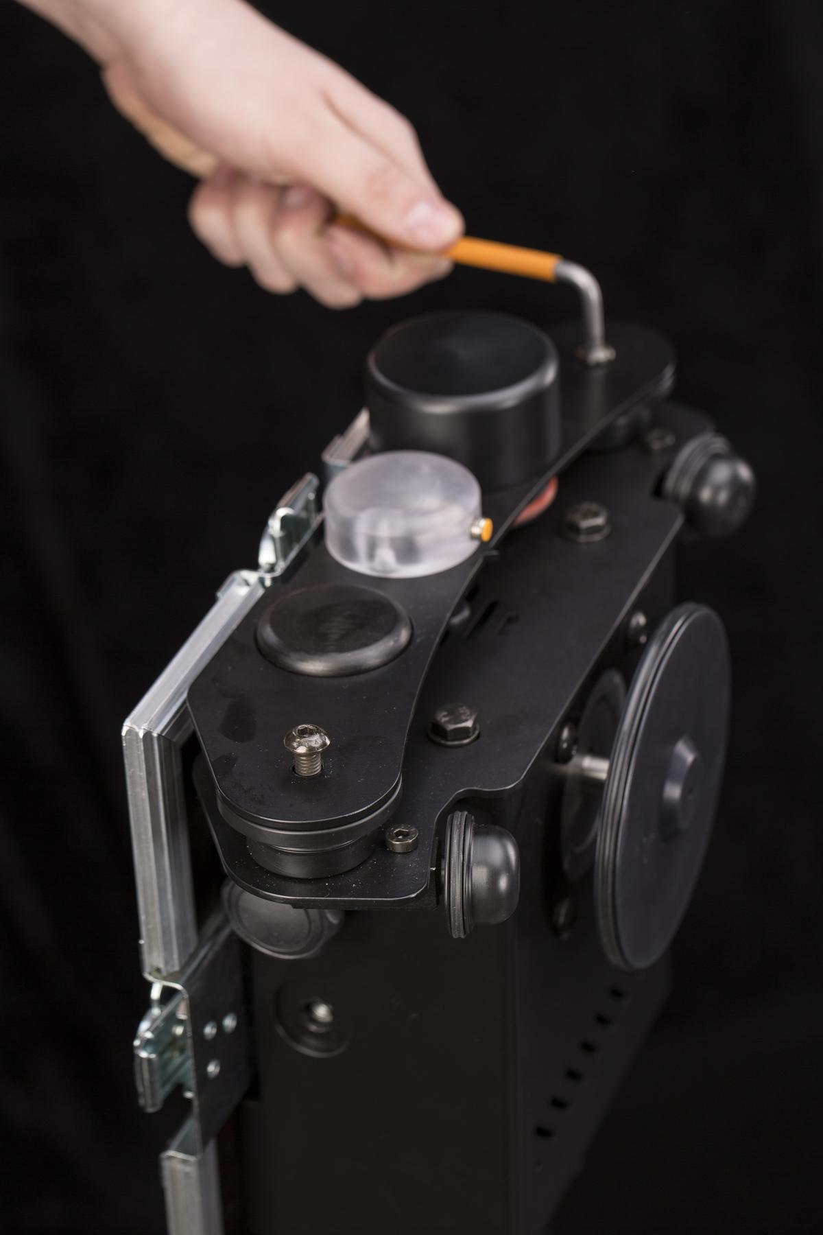
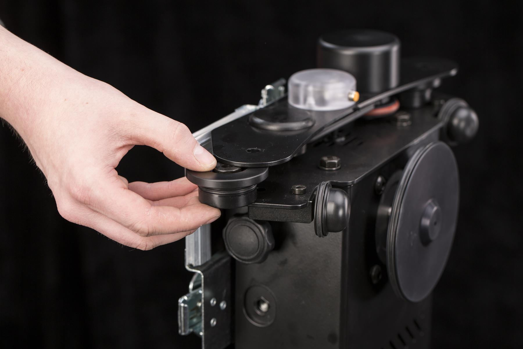
- To replace the X-rings of the support wheels on the side with the encoder, do not remove its cover. Just undo the hex screw.
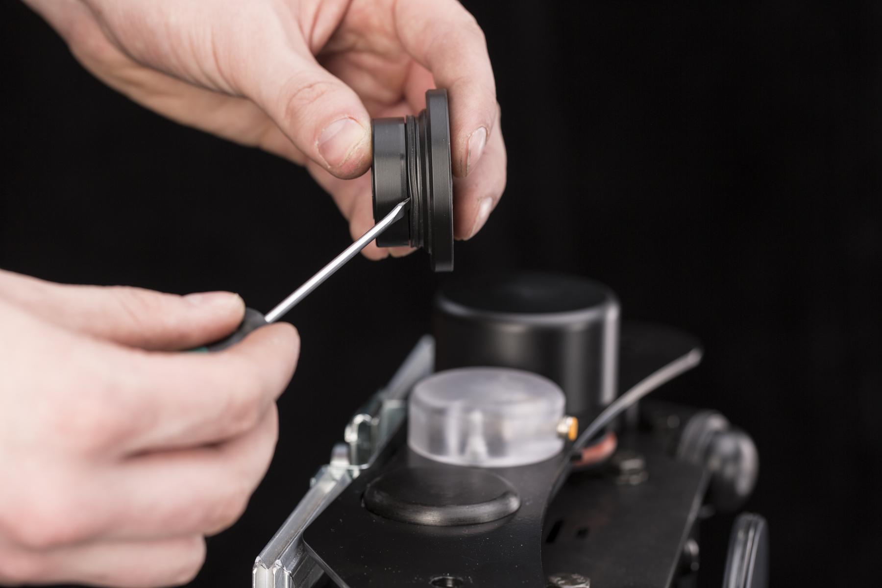
- Replace the X-ring the same way as on the previous wheels.
6.3 Firmware Update
To update the CASE’s firmware it is necessary to connect the CASE to the internet and the web based user interface. The process is described in the chapter 4.10.2 - Control the CASE.
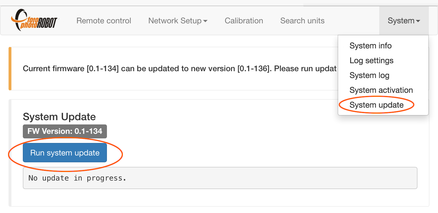
- In the menu go to System > System update. If the application indicates new firmware version, press “Run system update” to get the latest firmware version.
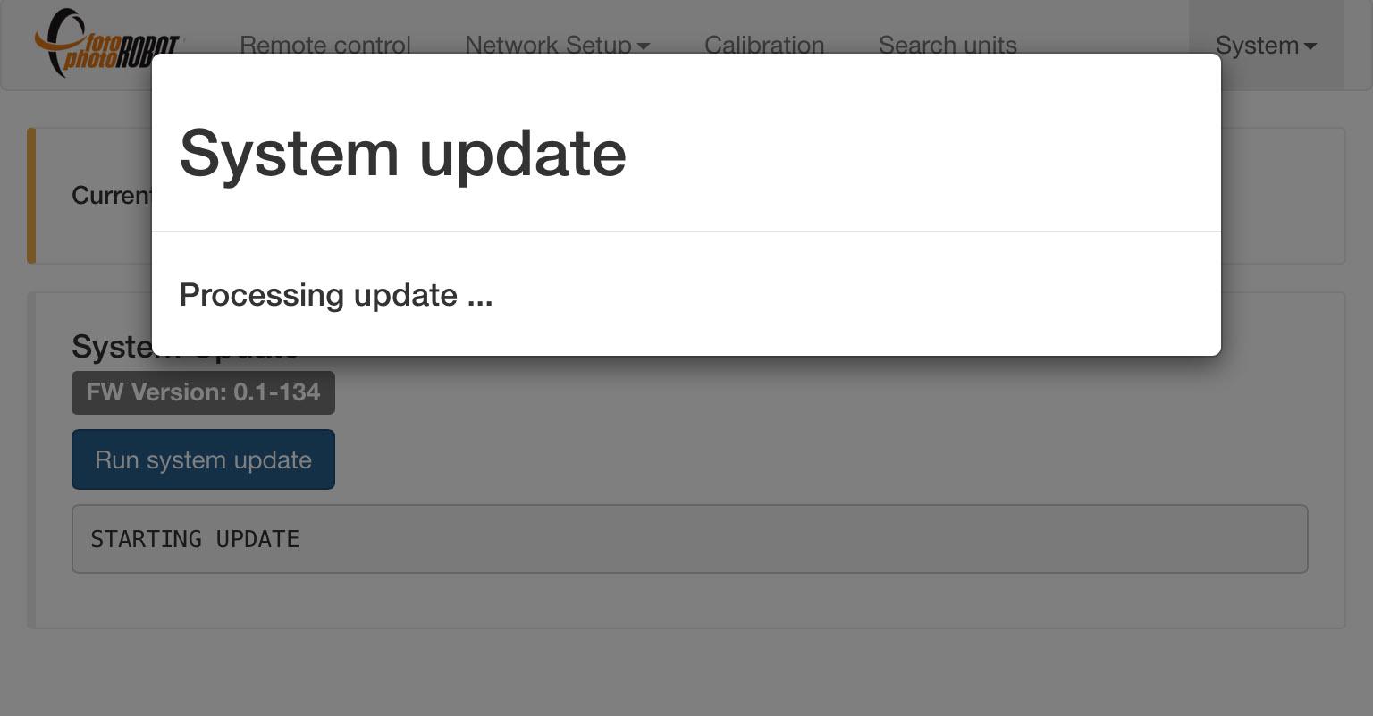
- The rest of the update is fully automated.
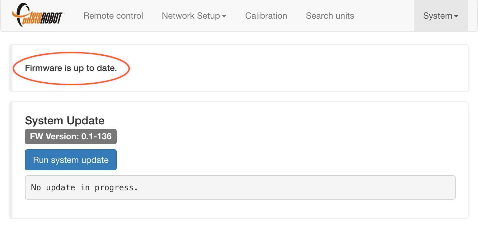
- The application indicates the firmware is up to date.
6.4. Activation
If you encounter an activation error, you may try to reactivate your CASE through the browser-based app (to connect to the app see chapter 4.3.1). Make sure the CASE is connected to the internet network. If the reactivation fails, please contact your CASE dealer for further assistance.
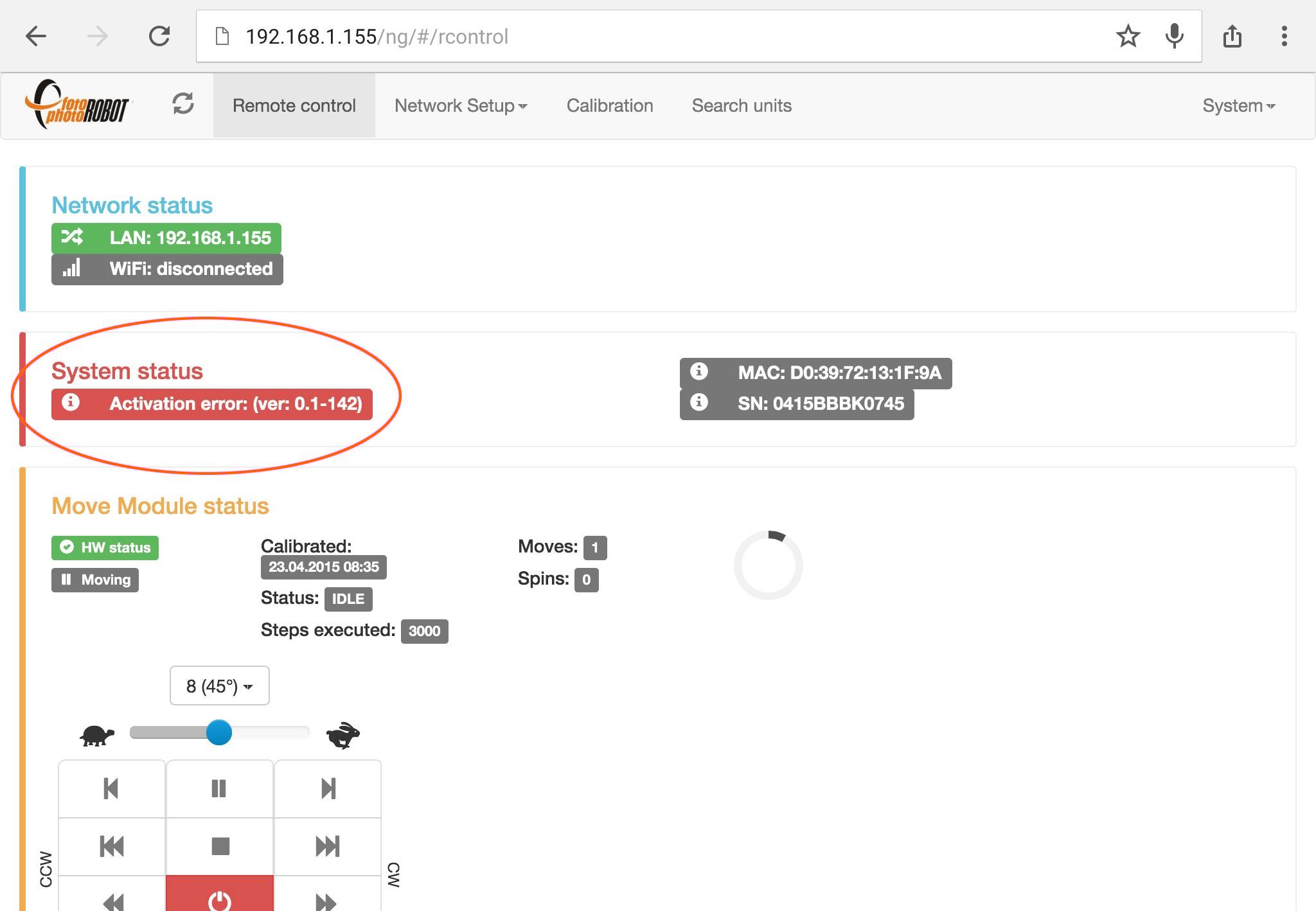
- An activation error is indicated in the System status box.
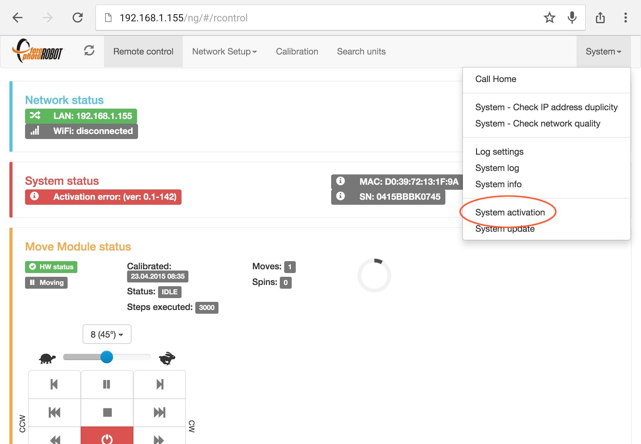
- To reactivate your CASE, go to menu System > System activation.
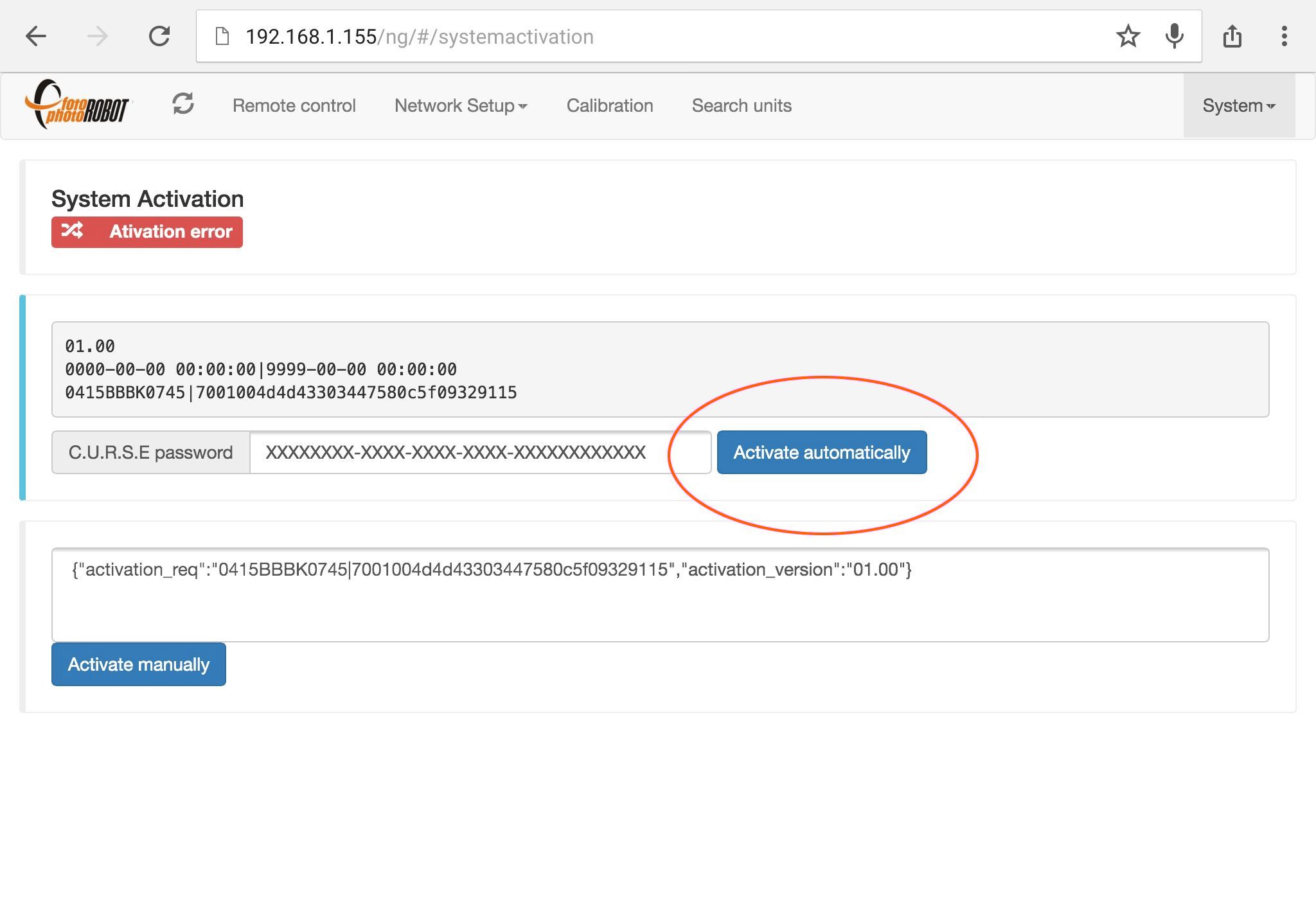
- Fill in your activation password and press Activate automatically.
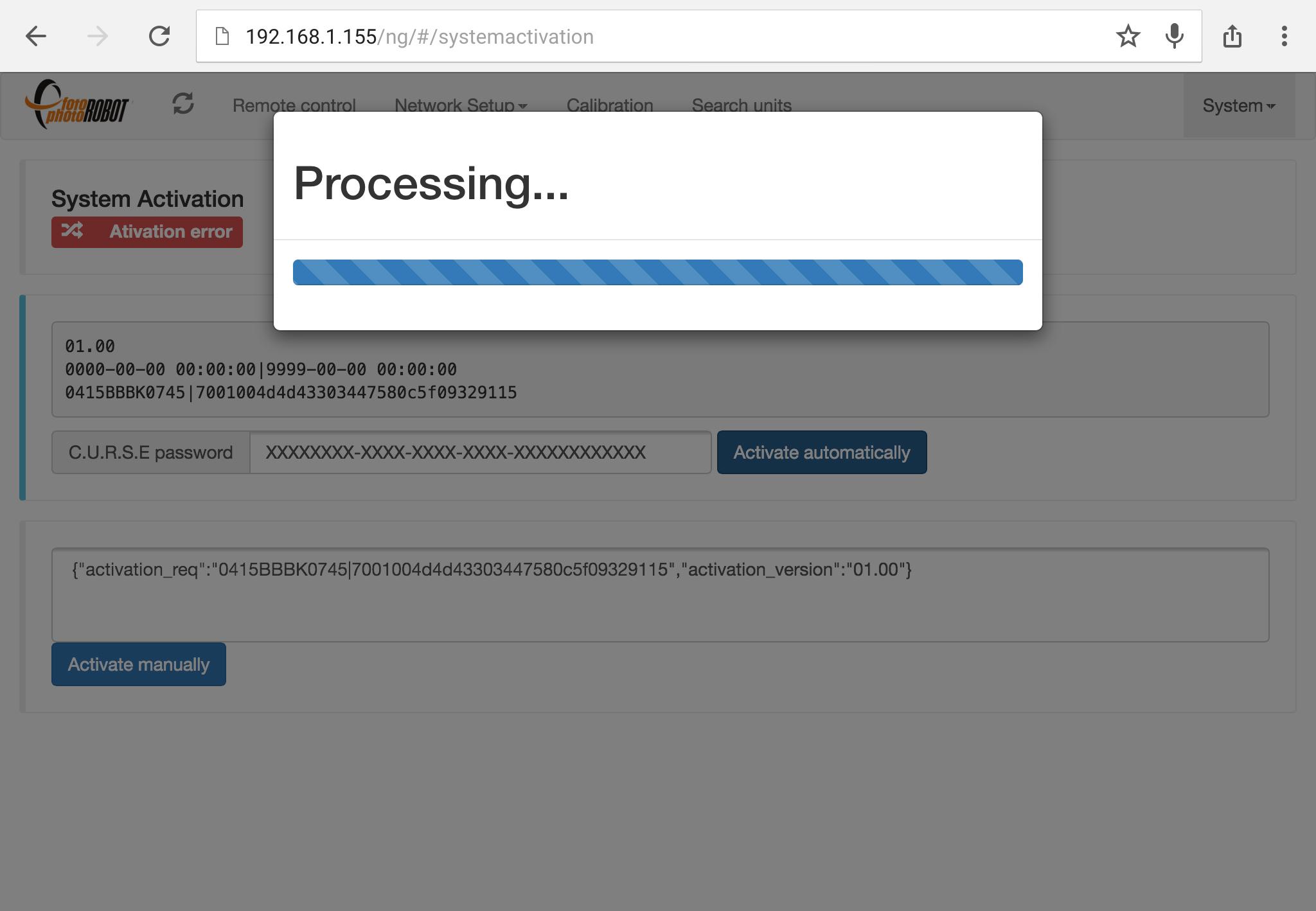
- The activation process takes about twenty seconds.
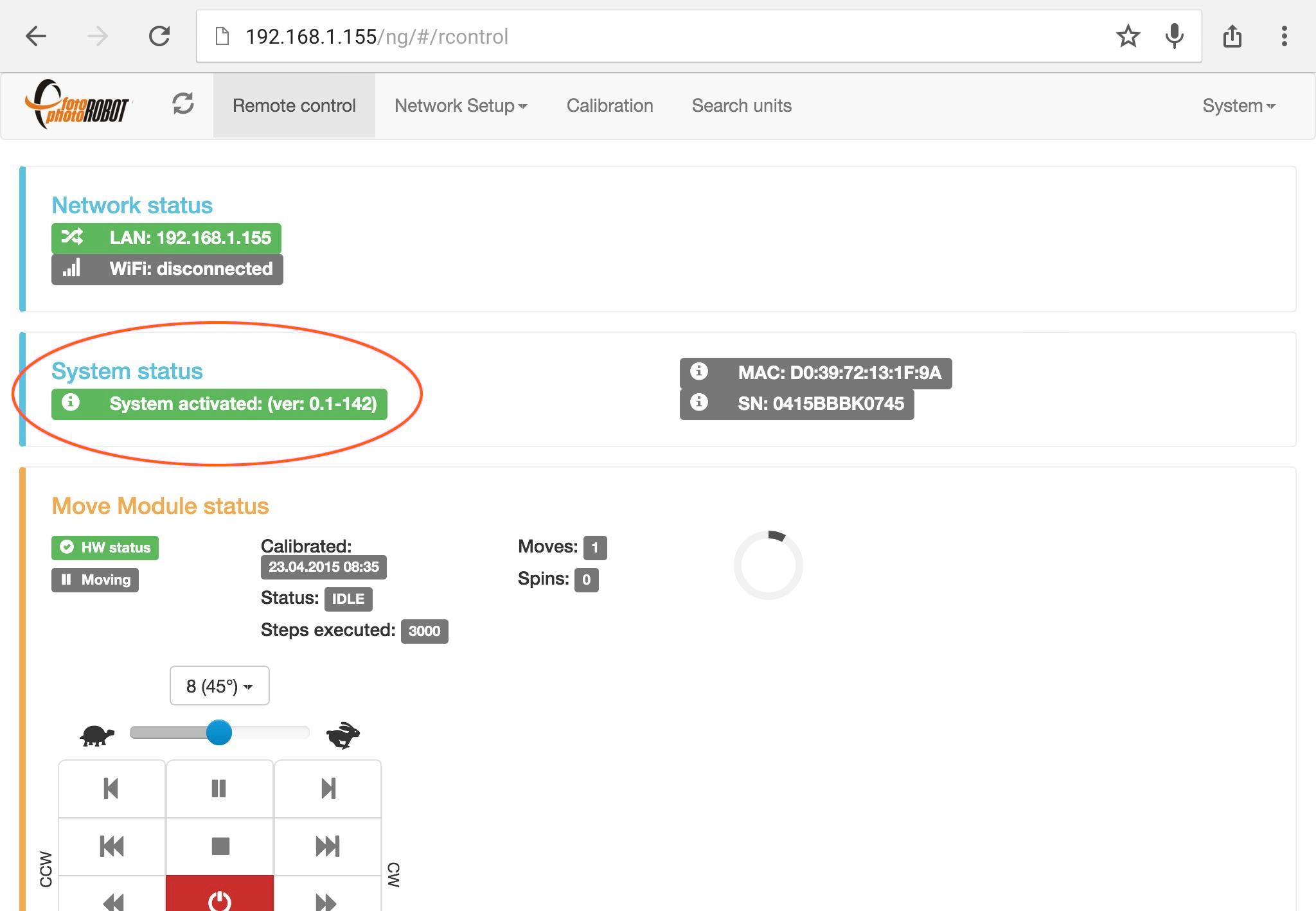
- Successful activation is indicated in the System status box.
7. FAQs
7.1. Do I need any equipment or accessories to run the CASE?
NO, everything necessary to get the CASE running is in the package. You just need a camera, a set of lights and a computer to control the CASE.
7.2. Do I need a computer to control the CASE?
YES, you need a computer which is running PhotoRobot Controls application to operate the CASE 850. The software controls the camera, lights, and robot, while processing the captured images immediately into publish-ready outputs — static images, 360° spin photography, video and 3D models. With an API license, further control options and third-party applications are also available.
For the computer specifications, refer to PhotoRobot System Requirements.
7.3. How long does it take to assemble the CASE?
For assembly of the CASE 850, it takes a matter of minutes — around 15 — to get the CASE from its packed state to action-ready.
7.4. Can I use continuous lights with the CASE?
YES, it is possible to use continuous lights with the CASE. Modern LED continuous lights are powerful and work well for many applications – even non-stop shooting of smaller products at lower speeds. Strobes remain the best choice for high-speed production, but continuous lighting is a perfectly good option for a wide range of use cases.
7.5. How do I trigger the camera?
In order to trigger the camera, it is possible to release the camera’s shutter using either a cable or wireless trigger connecting to the CASE, or by USB connecting to the computer.
7.6. Can I operate the CASE without internet connection?
YES, it is possible to operate the CASE without internet connection. However you need to connect it to some network to access it by the control app. It can be LAN, WLAN or a network provided by the CASE itself (using USB Wi-Fi module). The CASE can run strictly offline; in practice, however, it is often more convenient to keep some connectivity available — even if it is limited to metadata exchange only. For detailed deployment options, see the PhotoRobot Controls manuals, or contact PhotoRobot sales or technical support to discuss your intended setup, including fully offline, non-traceable deployments for field systems where the inability to trace the equipment is essential to operator safety.
7.7. What camera can I use with the CASE?
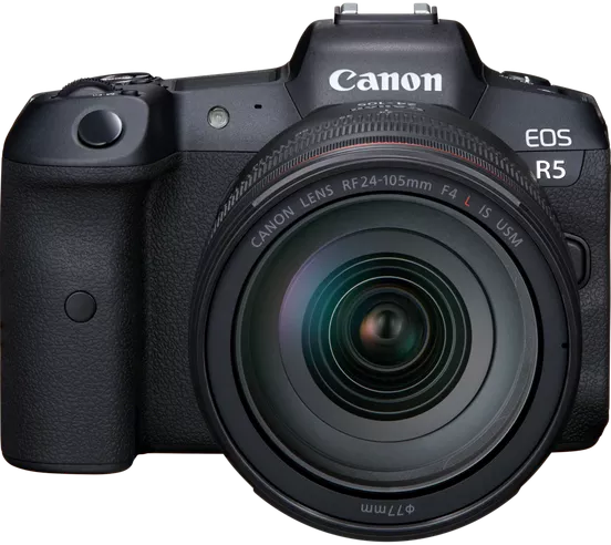
To see which cameras you can use with the CASE, the up-to-date supported camera is available online — refer to PhotoRobot Compatible Cameras and PhotoRobot Recommended Cameras. We can supply a cable or wireless trigger for supported models.
7.8. What strobes can I use with the CASE?
Any strobe lights can be used with the CASE. For the best results, use strobes that can be controlled directly from PhotoRobot Controls. The whole capture and preset workflow then runs fully automatically, with no need to adjust light intensity by hand.
7.9. Can I photograph on black with the CASE?
YES, it is possible to photograph on black using the CASE. The CASE gives great results either with black or white backgrounds. Please note that, by default, we only supply a white background. To photograph on black, you can simply remove the white background and place black velvet / fabric behind the CASE. We are also able to deliver a black background on demand. A black background can bring advantages in certain workflows – for example in photogrammetry.
7.10. Is it possible to photograph the product from below the glass plate?
YES, it is possible to photograph items from below the glass plate of the CASE 850. However, this is easier on a black background. To do so with a white background, you need to use the special freemasking mode in the PhotoRobot Controls application. Depending on the outputs you need, you can also use a different background altogether — for example for photogrammetry, where the capture and lighting workflow differs.
7.11. How much space do I need to run the CASE?
The minimum space necessary for the CASE with lights and the camera is only 2.5 x 2.5 metres and optimal space is 4 x 4 meters or more. Remember to also allow room for handling the products you photograph: thanks to the CASE’s high throughput, a relatively large number of items pass through during a single shift, so space to stage incoming and finished products keeps the workflow smooth.
7.12. Should I shoot RAW or JPEG?
For most production, we shoot JPEG and rely on the excellent in-camera processing of the Canon body (or Apple iPhone) to deliver finished images straight from the camera. If you still need RAW, PhotoRobot Controls can capture the RAW files in parallel — they are saved to a folder where you can edit or experiment with them freely in third-party tools.
7.13. What is the encoder used for?
The CASE 850 uses an encoder to provide the maximum accuracy of the glass plate rotation. It corrects the exact positioning at every stop.
Thanks to powerful hardware, the encoder reports the precise position of the glass plate to the control system 1000 times per second. This allows highly accurate capture without having to stop the plate – delivering exceptional productivity that no other systems match.
8. Technical Specifications
- Dimensions: 98 cm × 96 cm × 34 cm (38.6” × 38” × 13.4”)
- Weight: 62 kg (137 lbs)
- Shipping dimensions (cardboard box, without pallet): 106 cm × 105 cm × 43 cm (41.7” × 41.3” × 16.9”)
- Shipping weight (cardboard box, without pallet): 73 kg (161 lbs)
- Shipping weight (cardboard box, with IPPC certified pallet): 85 kg (187 lbs)
- Glass plate diameter: 85 cm (33.5”)
- Operating conditions: Interior use, placed on straight, hard, flat surface - water-level and stabilized - no interaction with liquids, enormous humidity or flammable gases - operation temperature 15-25° C
- Speed max: 2.1 s per revolution
- Speed min: ~ 4.5 mins per revolution
- # of images during one revolution: 1 - 3600 (possibly more for specialty use)
- Maximum load: 20 kg (44 lbs) - even distribution, without sharp edges
- Laser: Visible, continuous, integrated, cross type Class 1 Laser Product according to DIN EN 60825-1:2008-05λ = 650nm P0 ≤ 3.5mW
- Angular deflection: ± 1° per revolution
- Control unit: integrated, BeagleBone based
- Background: integrated, diffuse (white)
- Connectivity: LAN and Wi-Fi
- Calibration: yes, operator assisted
- Power supply: 100-240 V
- Operating software: built-in: web-based UI (Win, macOS, Linux, iOS) desktop: depending on manufacturer (Win, macOS)
- Camera compatibility: any camera with manual mode
- Lighting: either continuous or strobes

EOS Rebel Series
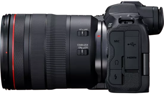
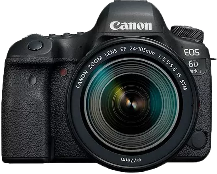
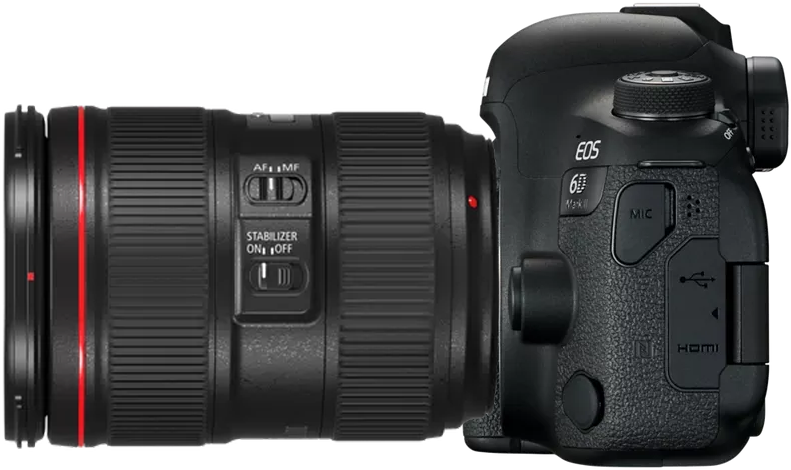
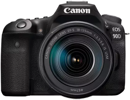
EOS DSLR Series
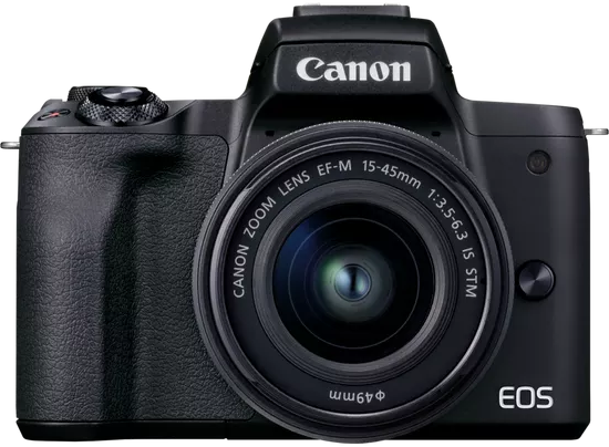
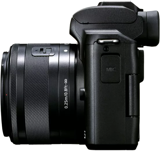
EOS M Mirrorless Series
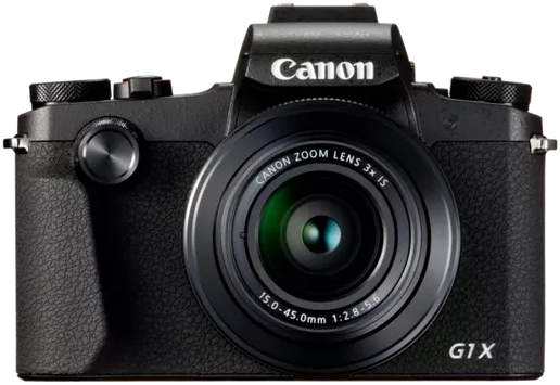
PowerShot Series
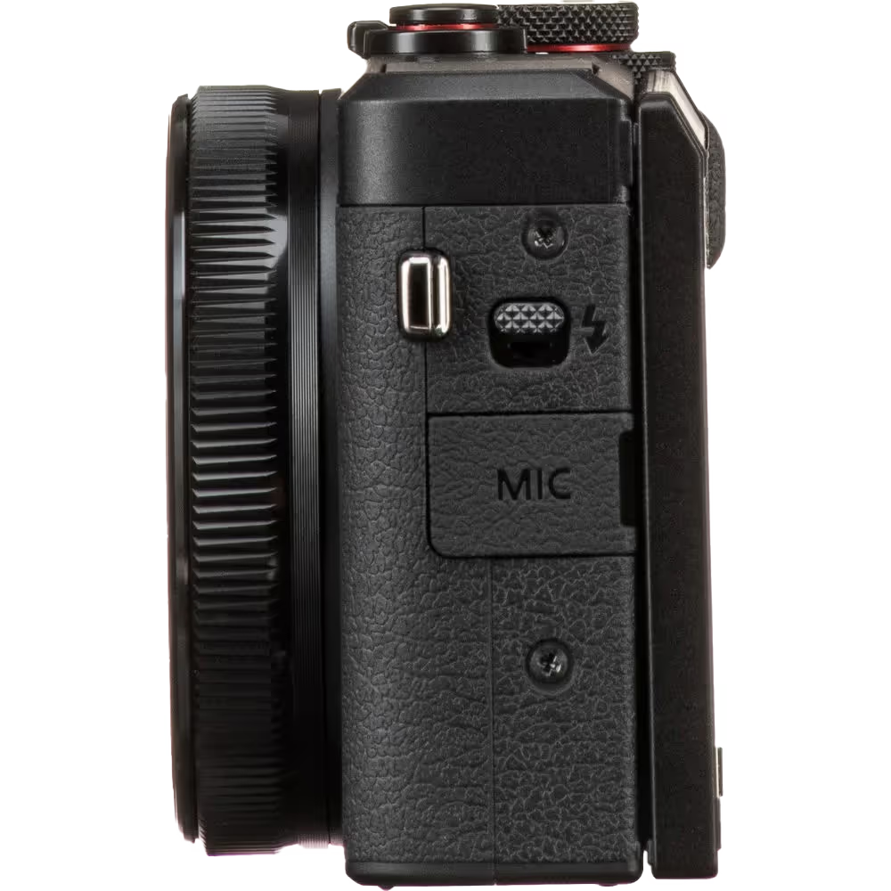
Close-Up / Handheld
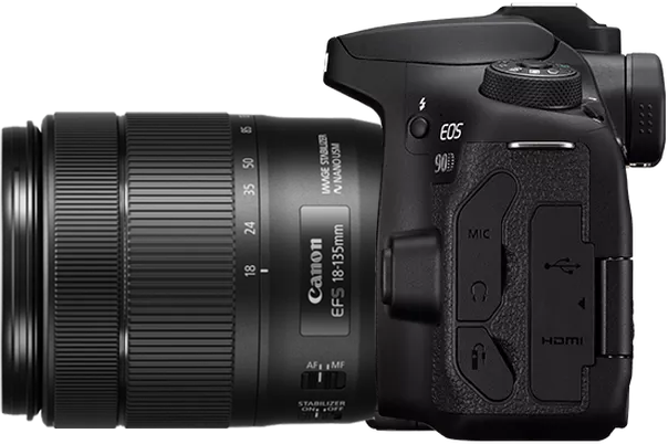
The Canon EOS Rebel Series offers beginner-friendly DSLR cameras with solid image quality, intuitive controls, and versatile features. Ideal for photography enthusiasts, these cameras provide reliable autofocus, vari-angle touchscreens, and Full HD or 4K video recording.
Connection
Resolution (MP)
Resolution
The Canon EOS DSLR Series delivers high-quality images, fast autofocus, and versatility, making it ideal for both photography and video production.
Connection
Resolution (MP)
Resolution
The Canon EOS M Mirrorless Series combines compact design with DSLR-like performance. Featuring interchangeable lenses, fast autofocus, and high-quality image sensors, these cameras are great for travelers and content creators seeking portability without sacrificing image quality.
Connection
Resolution (MP)
Resolution
The Canon PowerShot Series offers compact, user-friendly cameras for casual shooters and enthusiasts. With models ranging from simple point-and-shoots to advanced zoom cameras, they provide convenience, solid image quality, and features like image stabilization and 4K video.
Connection
Resolution (MP)
Resolution
The Canon Close-Up & Handheld Cameras are designed for detailed, up-close photography and video. Compact and easy to use, they offer precision focus, high-resolution imaging, and versatile macro capabilities—perfect for vlogging, product photography, and creative close-ups.