
PhotoRobot FRAME - Installation Manual
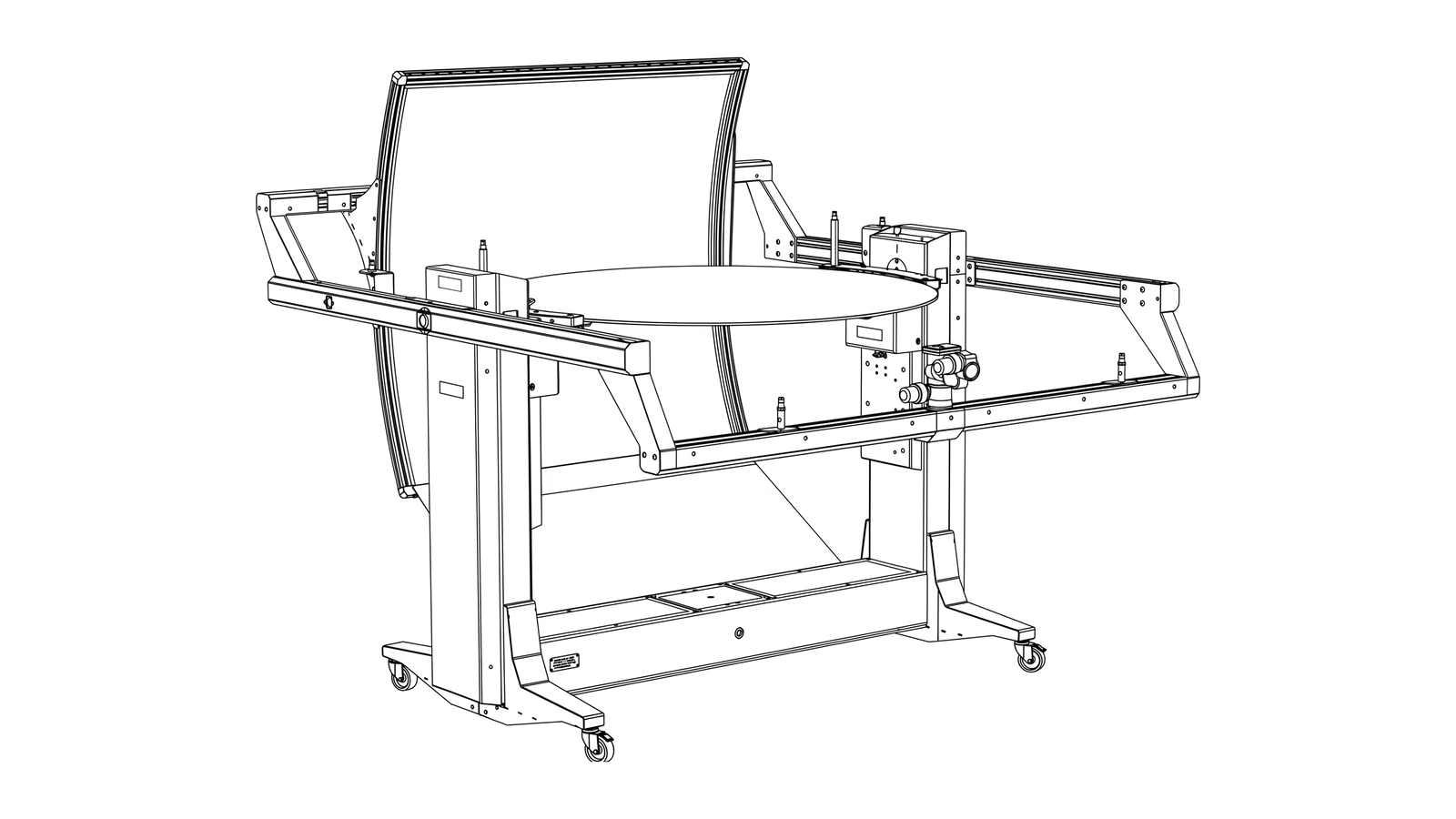
About this manual
This manual shows how a FRAME is unpacked, assembled, adjusted and handed over - step by step, in the order our technicians work. Positioning and aiming the six studio lights is covered in the separate FRAME Light Setup manual.
Who installs the FRAME
The FRAME is a 360 kg (794 lb) precision machine with a motorized glass turntable, a balanced swing arm and six studio lights. As standard, it is assembled and adjusted by two experienced PhotoRobot technicians over two days, followed by operator training.
If the FRAME is not installed by PhotoRobot technicians, you can assemble it yourself by following this manual. We strongly recommend official installation, though: many installation faults - balance, geometry, leveling, laser alignment, loose internal connections - cannot be diagnosed or corrected by phone, e-mail or video.
Official installation gives you a machine that is assembled, aligned and verified by the people who build it, and it keeps the full benefit of standard support tickets. If you install the FRAME yourself, we are happy to help as a paid on-site or remote service. Mechanical adjustments after a self-installation are not something we can resolve within standard support tickets, because they usually require hands-on work at the machine.
Safety first
- Read the PhotoRobot Safety Information & Instructions before you start.
- The FRAME weighs 360 kg; the crate weighs 650 kg. Never lift it by hand without the crew and equipment listed in chapter 02.
- The swing arm is not balanced during assembly. Always support it mechanically (chapter 04).
- Never move the arm electrically (Motor ON) before the camera and all four arm lights are mounted. The motors have no brake; an unbalanced arm can drop hard and damage the machine (chapters 04 and 13).
- Electrical work inside the machine (connector blocks, covers of the control electronics) is for PhotoRobot technicians only.
Chapters
| # | Chapter |
|---|---|
| 01 | Machine overview, terms and parts list |
| 02 | Tools, crew and site prerequisites |
| 03 | Unpacking, positioning and leveling |
| 04 | How the swing arm stays balanced (the "counterweight" principle) |
| 05 | Power, network and first power-on |
| 06 | Swing arm assembly (front section) |
| 07 | Cabling and sheet-metal covers |
| 08 | T-slot nuts and light holders |
| 09 | Background frame: assembly and squaring |
| 10 | Mounting the background and the black curtain |
| 11 | Glass plate, camera and shutter cable |
| 12 | Mounting the lights and the light stands (positions: separate FRAME Light Setup manual) |
| 13 | Leveling check, laser alignment and final adjustment |
| 14 | Handover checklist |
| 15 | Troubleshooting |
01 Machine overview, terms and parts list
1.1 What the FRAME is
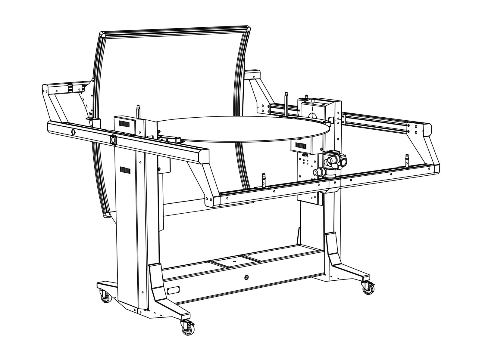
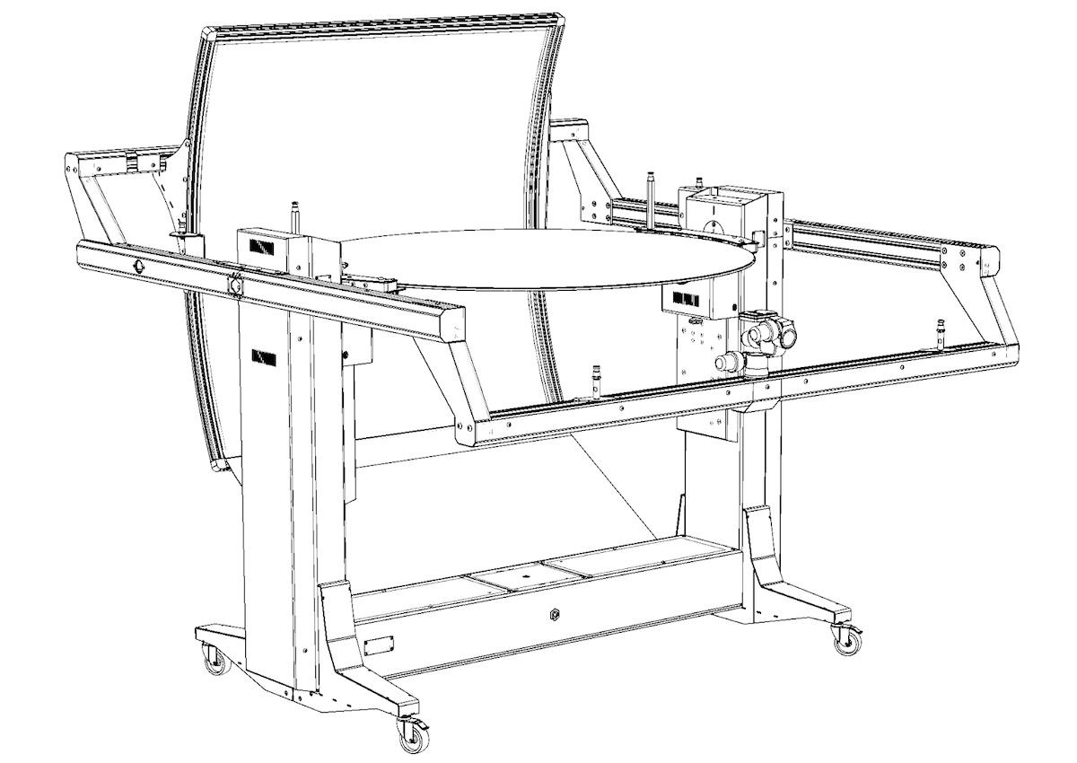
The FRAME combines a motorized turntable with a 1300 mm optical glass plate and a swing arm that carries the camera on one end and the white background on the other. Camera and background always stay opposite each other while the arm swings from -60 deg (below the glass) to +90 deg (above). The control unit is built into the machine body.
| Parameter | Value |
|---|---|
| Glass plate diameter | 1300 mm / 51.2 in |
| Load capacity | 20 kg / 44.1 lb |
| Minimum step / deviation per rotation | <= 0.1 deg / <= 0.5 deg |
| Shortest turn 0-360 deg | 4.5 s |
| Supply voltage | AC 115 / 230 V |
| Table input power | 750 W (to be confirmed) |
| Net weight | 360 kg / 794 lb |
| Transport weight / dimensions (W x D x H) | 650 kg / 1433 lb; 2050 x 1200 x 1500 mm (80.7 x 47.2 x 59.1 in) |
| Working dimensions (W x D x H) | 1925 x 2150 x 2260 mm (75.8 x 84.6 x 89 in) |
| Recommended working area (W x D x H) | 3 x 4 x 2.5 m (9.8 x 13 x 8.2 ft) |
1.2 Terms used in this manual
Use these words consistently - the old manual used several names for the same part.
| Term | Meaning |
|---|---|
| Machine body | The base with legs, leveling feet, casters, the turntable and the built-in control unit. |
| Uprights | The two vertical columns left and right of the glass that carry the spindle. |
| Spindle / central axis | The pivot of the swing arm on each upright. Cables leave the spindle here. |
| Swing arm | The rotating frame around the glass. It has a front section (camera end) and a rear section (background end). |
| Camera holder | The C-shaped front section that carries the camera mount, the front laser and the two front light holders. |
| Rear boom | The rear section that carries the background frame and the two rear lights. |
| Front / rear | Front = camera end of the arm, rear = background end, with the arm at 0 deg. |
| Left / right | As seen by a person standing at the front (behind the camera) and looking toward the background. (to be confirmed) |
| T-slot nut | The threaded nut that sits in the slot of an aluminum profile. Three types: A spring-ball, B rectangular, C small (chapter 08). Old manual names: "special silver nuts", "special support pegs", "threaded pegs", "threaded connectors", "special stones". |
| Background frame | The rectangular frame of curved and straight aluminum profiles that holds the white textile. |
| Rubber cord | The rubber reinforcement threaded into the sewn tunnels of the textile; it locks the textile into the profiles. |
| Threading jig | Small plastic block (about 1 in) used to guide the cord into the C-shaped profiles. |
| Black curtain | Heavy black nylon foil between the bottom edge of the background and the lower part of the machine. |
| Service GUI | The FRAME's built-in web interface (open its IP address in a browser). |
1.3 Parts list (what should be in the crate)
(to be confirmed)
| # | Part | Qty | Notes |
|---|---|---|---|
| P1 | FRAME machine body with uprights and rear boom (rear section mounted, front section reversed for transport) | 1 | 360 kg |
| P2 | Front section of the swing arm (camera holder) | 1 | mounted reversed for transport |
| P3 | Glass plate 1300 mm, with notch | 1 | in the crate slot |
| P4 | Casters | 4 | replace the black transport bases |
| P5 | White covers (left / right) | 2 | 2.7.1 |
| P6 | Sheet-metal cable covers | to be confirmed | 3 screws top + 3 bottom each |
| P7 | Light power cables 5 m | 4 | front lights / older models |
| P8 | Light power cables 3 m | 2 | background lights on newer models |
| P9 | Front light holders | 2 | |
| P10a | T-slot nuts type A (spring-ball) | (to be confirmed) + spares | attachment points on the arm (ch. 08) |
| P10b | T-slot nuts type B (rectangular) | (to be confirmed) + spares | inside the background profiles (ch. 08, 09) |
| P10c | T-slot nuts type C (small) + small screws | (to be confirmed) | sheet-metal cable covers (ch. 07, 08) |
| P11 | Background: white textile with sewn tunnels, rubber cord, 2 curved "X" profiles, 2 straight crossbars, corner couplings, side brackets, template | 1 set | may ship assembled |
| P11b | Background washer kit (black, 3D printed): X-shaped shims for the background frame corners + round washers | 1 kit | X-shaped shims only if needed (ch. 09). Round washers are not used on the FRAME (they are for C1300/C850; packed in the standard kit to keep it simple) |
| P12 | Threading jig | to be confirmed | |
| P13 | Black curtain (nylon foil) | 1 | |
| P14 | Shutter cable set: Canon N3 and 2.5 mm jack adapters + coupler | 1 | plastic bag |
| P15 | Manfrotto 405 geared head | 1 | camera mount |
| P16 | Active USB extension and camera cable, 10 m | 1 | |
| P17 | Networking kit + 19 in rack case | 1 | see Network Equipment manual |
| P18 | Lights: set of 6 - 2 background lights with reflectors, 2 product lights with softboxes (arm), top light and bottom light each with a 90 x 120 cm softbox | 1 set | variant per order; positions in the FRAME Light Setup manual |
| P19 | Boom stand LS-13B with boom (about 1.5 m, pin end) and boom counterweight, for the top light (or ceiling rail system, if ordered) | 1 | separate cardboard box on the pallet, boom parts in plastic foil |
| P19b | Low floor stand LS-3B (no center column), for the bottom light | 1 | separate cardboard box on the pallet |
| P20 | Short hex key for casters / leveling feet | 1 | supplied - easy to overlook |
02 Tools, crew and site prerequisites
2.1 Crew and time
| Phase | Typical time (experienced crew) |
|---|---|
| Unpack, lift off the pallet, position | about 2 h |
| Mechanical assembly (arm, covers, cables, background, lights, glass) | at least 2 h |
| Leveling, laser alignment, calibration | about 3 h |
| Tests, handover | remaining time of day 2 |
- Two PhotoRobot technicians, two days. Several steps need two people at the same time (fitting the camera holder over the T-slot nuts on both sides, lifting the glass, lowering the machine from the pallet).
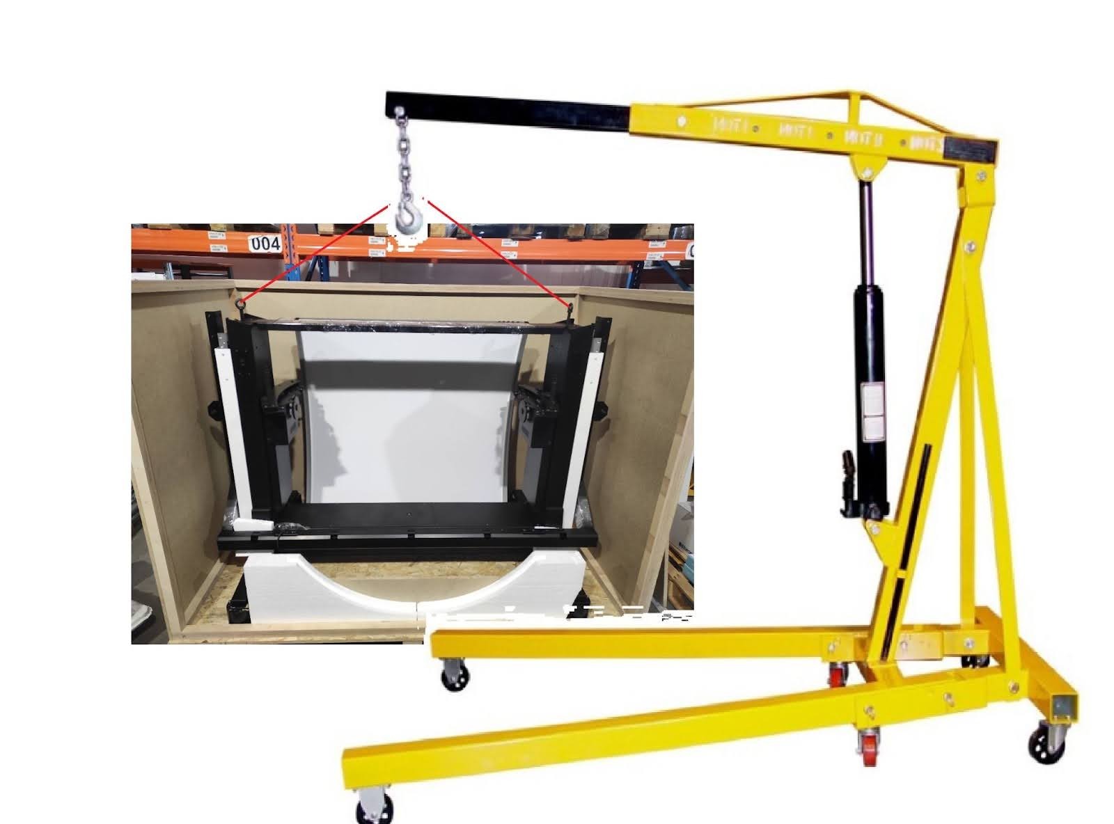
- Lifting: the machine (360 kg) is lifted off the pallet with slings rated 400 kg or more and a forklift or shop crane, or by at least four people .
- Operator training is a separate block after installation (PhotoRobot recommends three days of training for FRAME).
2.2 Tools
| Tool | Used for |
|---|---|
| Lifting slings, >= 400 kg | lifting the machine by the handles on the top of the frame |
| Forklift, pallet jack or shop crane | lifting / moving the crate and the machine |
| Metric hex (Allen) key set + the short hex key supplied with the FRAME | casters, leveling feet, arm and covers |
| Socket wrench 16-18 mm | laser adjustment from outside the uprights |
| Screwdrivers (Phillips, flat) | covers, connector blocks (technician only) |
| Torque wrench | (to be confirmed) |
| Spirit level, 600 mm or longer (or digital level) | leveling the machine body and the glass |
| Tape measure (5 m) | squaring the background, light positions |
| Light stand, camera tripod or sturdy chair | supporting the swing arm during assembly (chapter 04) |
| Cable ties, painter's tape, marker, round sticker | cable routing, laser center marks |
| Gloves, safety shoes | handling the 360 kg machine and the glass |
| Laptop with Chrome/Edge on the customer LAN | Service GUI, PhotoRobot Controls |
2.3 Site prerequisites (customer confirms before the technicians travel)
Send this list to the customer with the order confirmation and check it again one week before travel.
Access and handling
- Doors, corridors and elevators fit the crate: 2050 x 1200 x 1500 mm (80.7 x 47.2 x 59.1 in), 650 kg.
- Forklift or pallet jack and a person to operate it are available on day 1.
- The crate can be opened at the installation spot or close to it (the unpacked FRAME rolls on casters).
Space and floor
- Free working area at least 3 x 4 m, ceiling 2.5 m or more (9.8 x 13 x 8.2 ft); space to walk around the machine and room in front of it for the boom stand LS-13B and the floor stand LS-3B.
- Solid, flat, hard floor. No carpet or soft vinyl. On wooden floors, a weight-distribution board.
Power
- Grounded sockets, 115 V or 230 V, matching the rating plate.
- The end power lead for local sockets is supplied by the customer (IEC 60320 C13/C14 on the machine side), unless agreed otherwise. No travel adapters for the lights.
- Separate circuits for the lights: plan no more than two strobes per circuit/phase ; the FRAME itself needs a single standard circuit.
Network
- The customer LAN meets the PhotoRobot Networking Prerequisites:
DHCP, TCP 7777/7778, UDP broadcast 6666, internet access,
*.photorobot.comandas-unirobot.azurewebsites.netallowed, no proxy. - Or the PhotoRobot networking kit is used (Network Equipment) with one internet uplink.
- Wi-Fi is available for the lights and the Locator app.
People and timing
- Delivery has arrived and customs are cleared before the technicians travel.
- A local contact with authority over IT and facilities is present on both days.
- Sample products for the test shoot are on site from the afternoon of day 2.
03 Unpacking, positioning and leveling
Step 3.1 - Open the crate
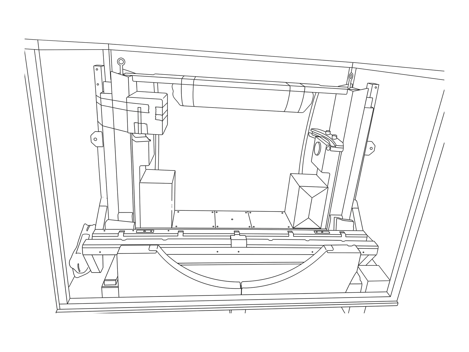
- Remove the top cover of the crate, then the rear cover.
- Take out all loose parts around the machine, including the glass plate. Keep the glass in its packing and put it somewhere safe and flat.
- Collect the separate boxes on the pallet next to the crate: the two light stands come in their own cardboard boxes and the boom parts are wrapped in plastic foil - they are easy to miss.
- Lay out the loose parts and check them against the parts list (1.3). Look for the small-parts bags (T-slot nuts, short hex key, shutter adapters, threading jig) now and sort the T-slot nuts by type (A, B, C - chapter 08). Missing or mixed-up small parts are the most common blocker later.
- In the background washer kit you will find X-shaped shims (used on the FRAME if needed, chapter 09) and round black washers. The round washers are not for the FRAME - they belong to the C1300/C850 tables and are in the kit only to keep one standard kit. Set them aside so nobody looks for a place to fit them.
Checkpoint: all parts P2-P20 found. If anything is missing, report it to PhotoRobot before you continue.
Step 3.2 - Release the machine from the pallet
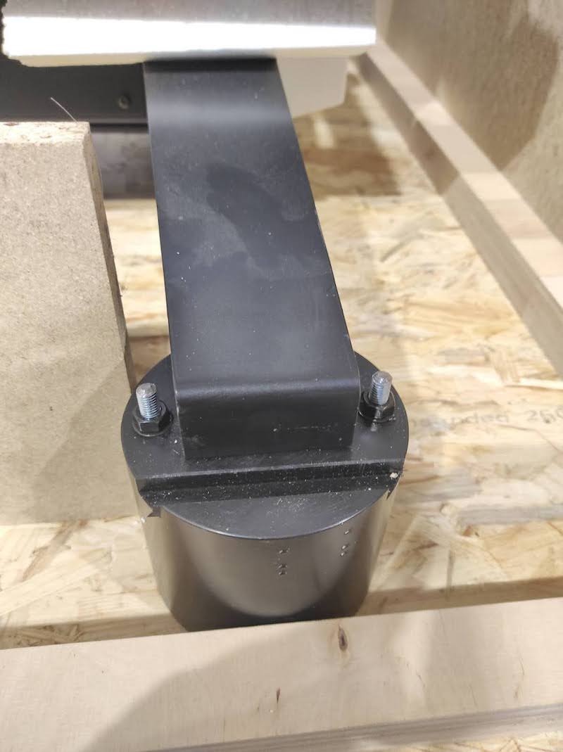
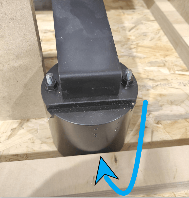
- Remove the two nuts on each of the four black transport bases (8 nuts) .
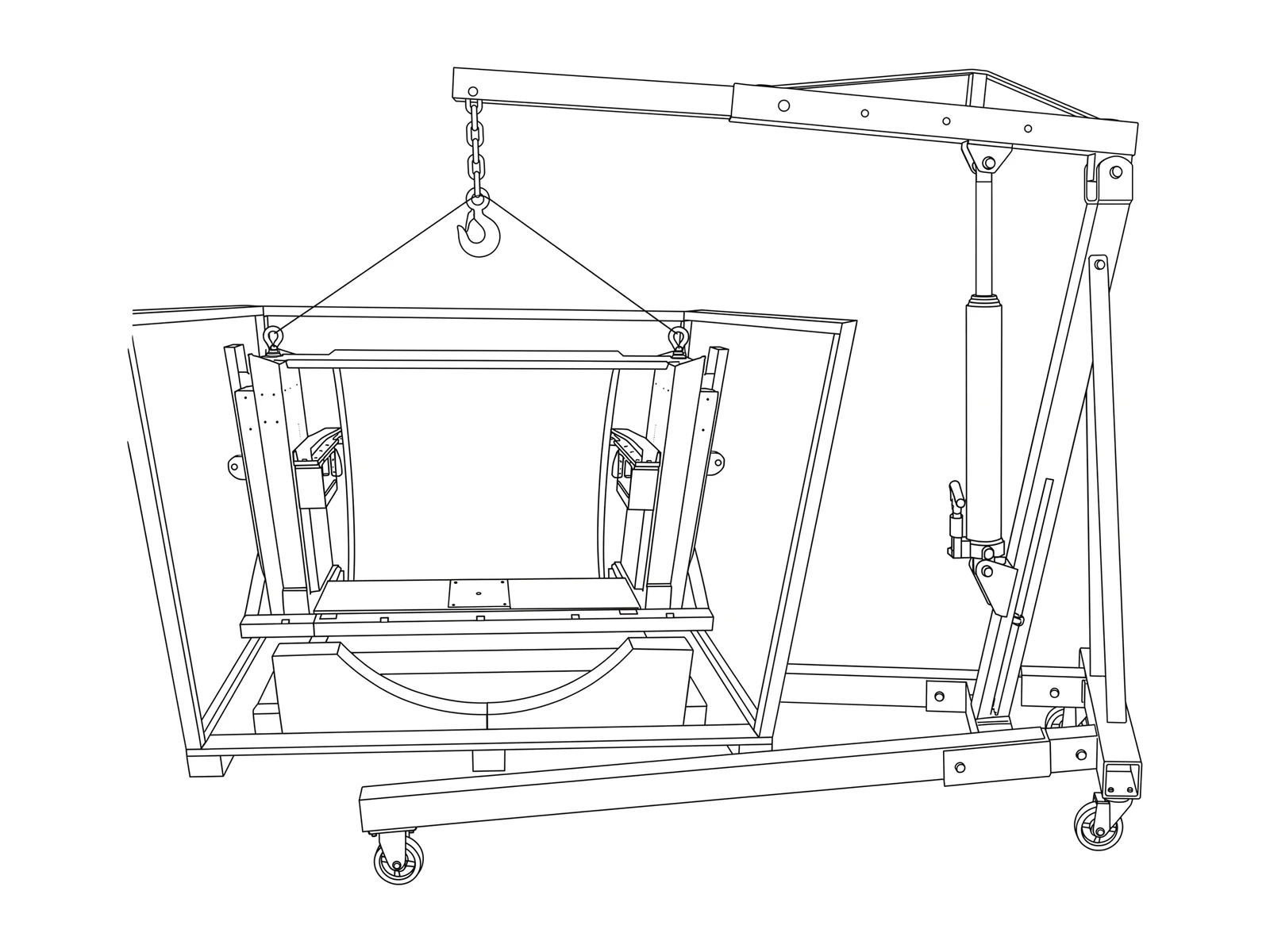
- Thread lifting slings (rated >= 400 kg) through the handles on the top of the machine frame.
- Lift the machine with a forklift or shop crane just enough to free the bases.
- Unscrew the four black transport bases from the bottom of the legs.
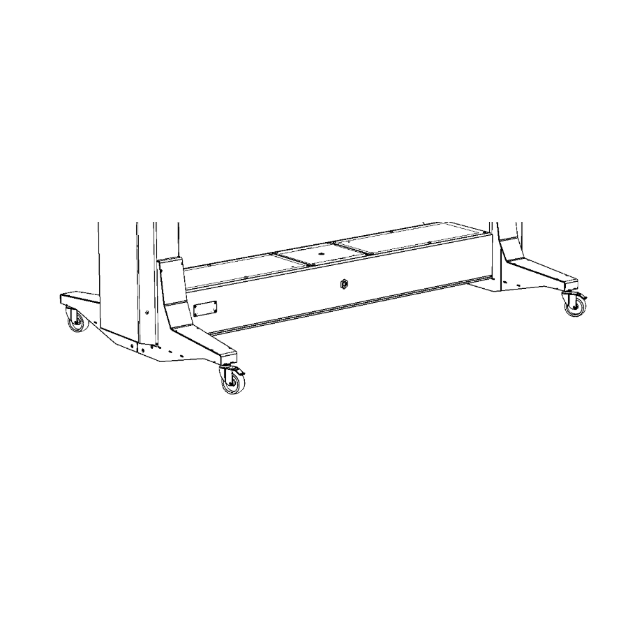
- Fit the four casters in their place and tighten them.
- Lower the machine onto the casters and remove the slings.
WARNING The machine weighs 360 kg (794 lb). Nobody may stand or put hands under the raised machine.
Checkpoint: the machine stands on four casters, all caster bolts are tight.
Step 3.3 - Remove transport parts
- Remove all packing material, straps and transit bolts.
- (to be confirmed)
- (to be confirmed)
Step 3.4 - Position the machine
- Note the orientation: the power switch and power socket are on the back of the machine body .
- Roll the machine to its final position in the working area (chapter 02). Leave room to walk around it.
Step 3.5 - Stand the machine on its leveling feet
The FRAME must not be calibrated while standing on its casters - on casters it is not stable and calibration will drift.
- Using the short hex key supplied with the machine, lower the leveling feet / raise the casters until the machine stands firmly on its feet .
- Put the spirit level on the machine body across and along the machine. Adjust the feet until it is level. Target: (to be confirmed).
- If a caster screw is stiff, stop and check it is not cross-threaded - do not force it with a long key.
Checkpoint: the machine does not rock when pushed at the corners; level in both directions within to be confirmed. Re-check leveling in chapter 13 after everything is mounted.
04 How the swing arm stays balanced
WARNING - read before you power on
Never move the swing arm electrically (Motor ON, arm commands in the Service GUI or Controls) until the camera on its head and all four arm lights (2 rear, 2 front) are mounted. The arm is balanced only when the complete set is on it. Moving it with parts missing can damage the machine. The motors have no mechanical brake or lock - if the arm is out of balance, they will not stop it from swinging down.
Following the old power-on order (Motor ON and raise the arm to 0 deg while the front parts are still missing) has already made the arm come down hard during an installation.
4.1 The principle
The swing arm is a rocker: it pivots on the spindles in the two uprights, like a seesaw.
- The front end carries the camera holder, the camera on its head and the two front lights.
- The rear end carries the background frame with the textile and the two rear background lights.
The machine is designed so that this complete set is the counterweight: front and rear balance each other around the spindle. There are no separate counterweights to add and no balance adjustment during installation - you simply mount everything that belongs on the arm. The softboxes are light; whether they are on or not makes little difference, but the lights themselves and the camera must be on.
4.2 What this means during assembly
During assembly the arm is out of balance on purpose: it ships with the rear section mounted and the front section removed or reversed for transport. With only the rear section on, the rear end is heavier and wants to swing down.
Rules during assembly:
- Restrain the rear of the arm mechanically the whole time (light stand, camera tripod or a sturdy chair under the rear beam; for overnight, block it so it cannot move).
- Move the arm only by hand, slowly, with one person holding the rear end.
- No Motor ON until the camera and all four arm lights are mounted (chapter 12). The first electrical arm movement is in chapter 13.
4.3 Assembly order (updated 29 Oct)
- Rear section on, background not yet mounted, rear beam supported.
- Mount the front section (camera holder) - chapter 06.
- Check the geometry (both sides flush with the central axis, arm straight).
- Mount the background - chapters 09 and 10. Keep the support: the rear is now clearly heavier.
- Mount the front light holders, all four lights and the camera head with the camera - chapters 08, 11, 12.
- The arm is now close to balanced. Remove the support carefully while one person holds the arm. It should stay roughly where it is left.
- Only now: Motor ON and first electrical movement - chapter 13.
4.4 Signs that something is wrong
| Symptom | Likely cause | What to do |
|---|---|---|
| Arm swings rear-down when released by hand | Front parts (camera, front lights) not mounted yet | Expected - support it; finish the assembly |
| Arm drops when Motor ON is pressed or an angle is commanded | Arm moved electrically before the full set was mounted | Stop. Support the arm; mount camera and all four lights; then check for damage (chapter 15) |
| Arm sags or struggles with the complete set mounted | A part missing on one end, or a motor not getting full power | Check all four lights and the camera are on. Then a PhotoRobot technician checks the wiring (chapter 15) |
The power cord, plug adapter or wall circuit is very unlikely to be the cause: the FRAME draws well under the rating of a standard 15 A circuit (750 W at 115 V is about 6.5 A).
05 Power, network and first power-on
You connect power and network early so you can check that the FRAME is visible on the network. You do not move anything with the motors in this chapter.
WARNING - changed from the old manual. The old manual (2.5) said: power on, Motor ON, raise the arm to 0 deg, then mount the front part. Do not do this. With the front section, camera and lights missing, the arm is out of balance and the motors have no brake - it can come down hard and the machine can be damaged. Motor ON and arm movement come only in chapter 13, after the camera and all four arm lights are mounted.
Step 5.1 - Connect power (switch off)
- Check that the machine's power switch (back of the machine body) is off.
- Check that the rating plate matches the local supply (115 V or 230 V).
- Connect the power cord to the machine. Plug it into a grounded socket last.
Step 5.2 - Connect the network
- Set up the PhotoRobot networking kit as described in Network Equipment & Wiring.
- Connect at least: internet uplink, the laptop/workstation, and the FRAME.

Step 5.3 - Power on in the right order
Before you switch the FRAME on, make sure the rear of the arm is mechanically supported (chapter 04).
- Power on the router. Wait about 2 minutes until it is fully up.
- Power on the computer.
- Power on the FRAME last.
Step 5.4 - Find the FRAME and open the Service GUI (read-only check)
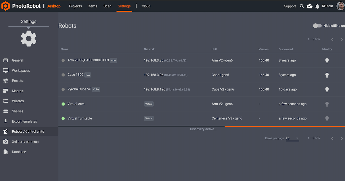
- In PhotoRobot Controls (CAPP) go to Settings > Robots / Control units. A green dot means the robot is online. Clicking the row opens the robot's web interface and makes its LED blink. Alternatives: PhotoRobot Locator (iOS) or FRFind (macOS/Windows) from PhotoRobot Account > Downloads.
- Open the robot's IP address in a browser. The Service GUI opens.
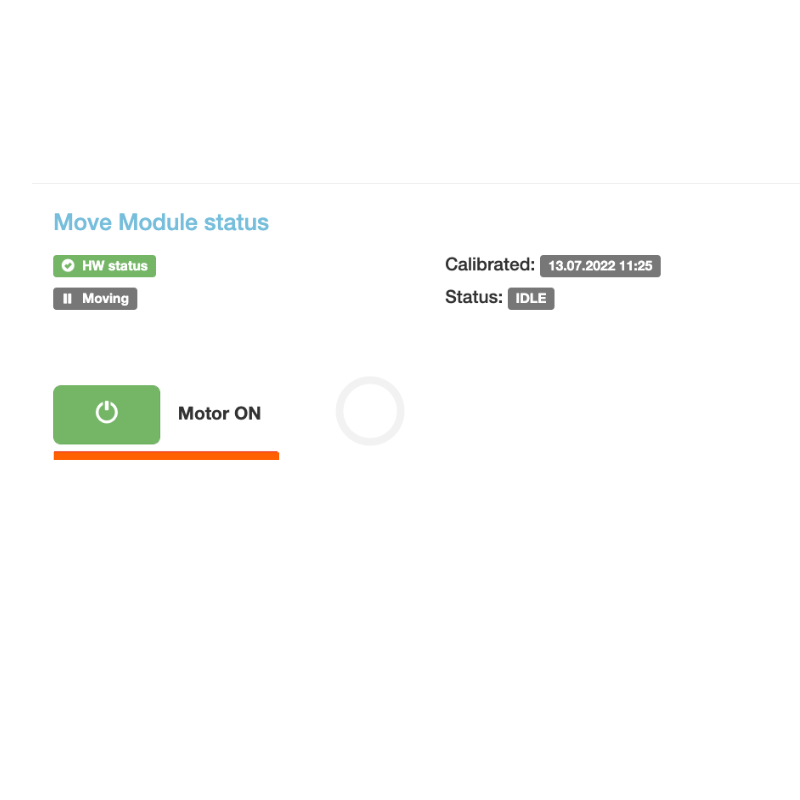
Checkpoint: Service GUI shows HW status OK. Do not press Motor ON yet.
Then switch the FRAME off again until the mechanical assembly is complete, or leave it on with the motors off.
06 Swing arm assembly (front section)
People: 2 (one on each side). Before you start: chapter 04 read, rear beam supported.
WARNING All arm movement in this chapter is by hand, with the motors off. Do not use Motor ON or the Service GUI to position the arm - the arm is out of balance until the camera and all four lights are mounted.
Step 6.1 - Remove the transport-reversed front section
For transport the front section (camera holder) is mounted reversed (flipped over).
- Support the front section, then remove its four bolts.
- Lower it and put it aside on a clean, padded surface.
CAUTION The shutter cable comes out of the spindle on the side where the arm connects. When you move or rotate any part of the arm, watch this cable - it is easy to pinch or cut.
Step 6.2 - Bring the arm to the assembly position
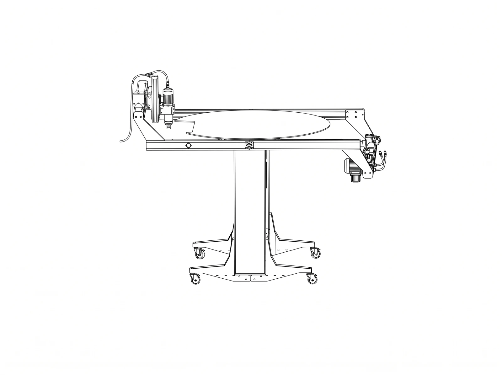
- By hand, with one person holding the rear end, gently swing the rear section backward until the future camera position is at 0 deg - the background end is behind the machine, the front end is open.
- Support the rear beam in this position (chapter 04).
Step 6.3 - Fit the front section over the T-slot nuts
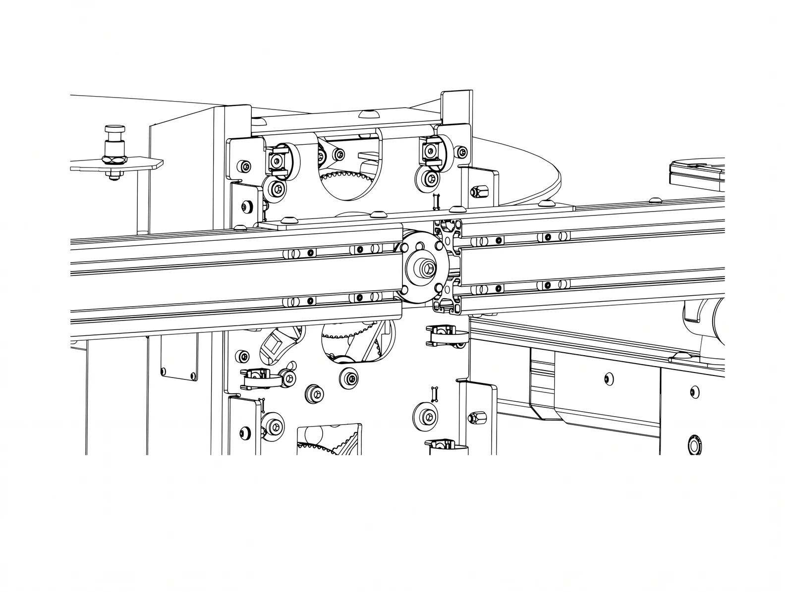
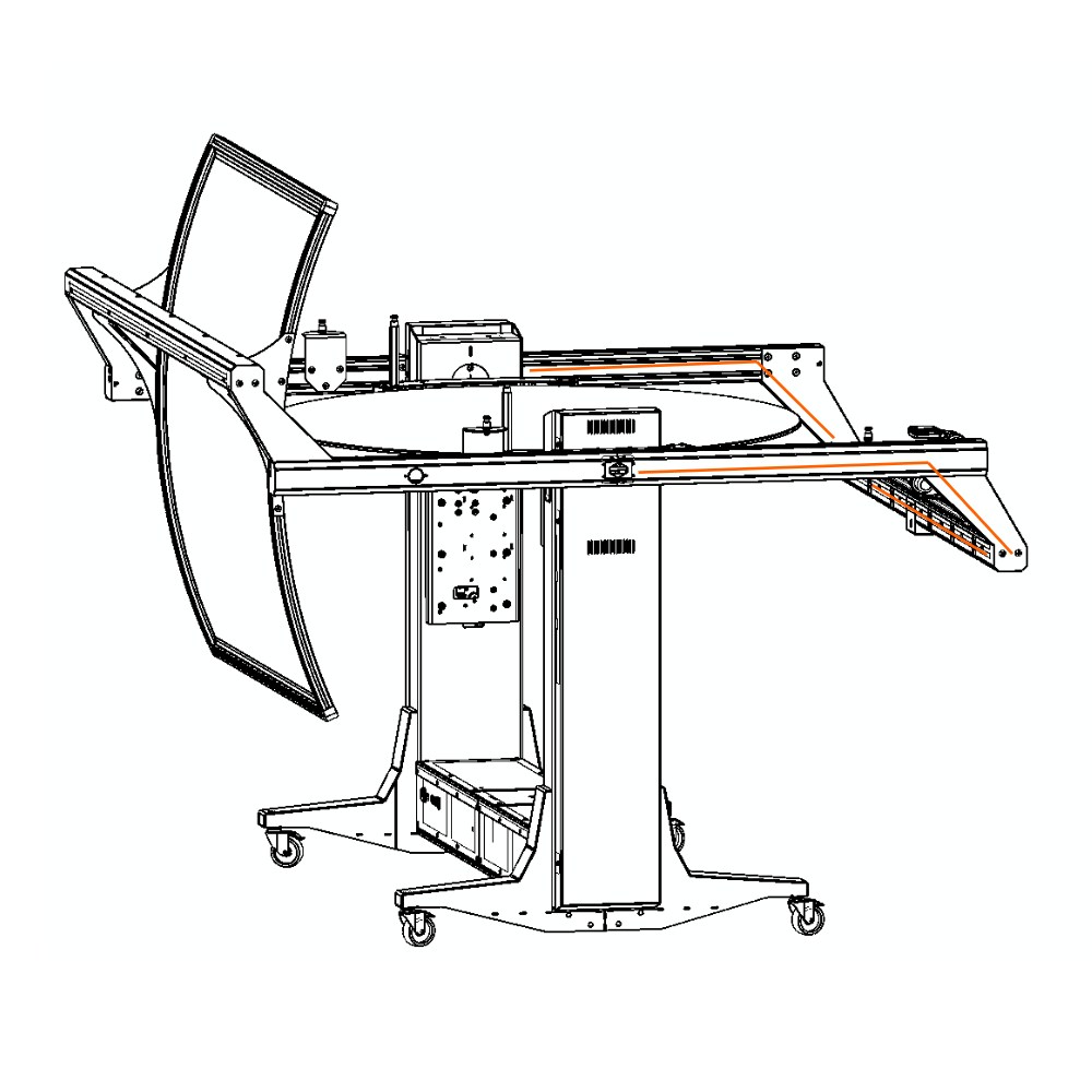
On each side of the arm there are 6 T-slot nuts in 2 rows of 3 in the profile slots .
- Check that all 12 nuts are in the slots and roughly aligned with the holes of the front section. If any are missing, see chapter 08 - do not dismantle other parts.
- With one person on each side, slide the C-shaped front section onto the nuts on both sides at the same time. Getting the first nuts in on one side tends to push the other side out of line - work together and call out.
- Push both sides up to the central axis so they are flush with it.
Step 6.4 - Tighten
- Insert and tighten the six screws on each side into the T-slot nuts. Torque: (to be confirmed).
- Screw the connecting parts of the arm tightly onto both sides of the machine. Torque: (to be confirmed).
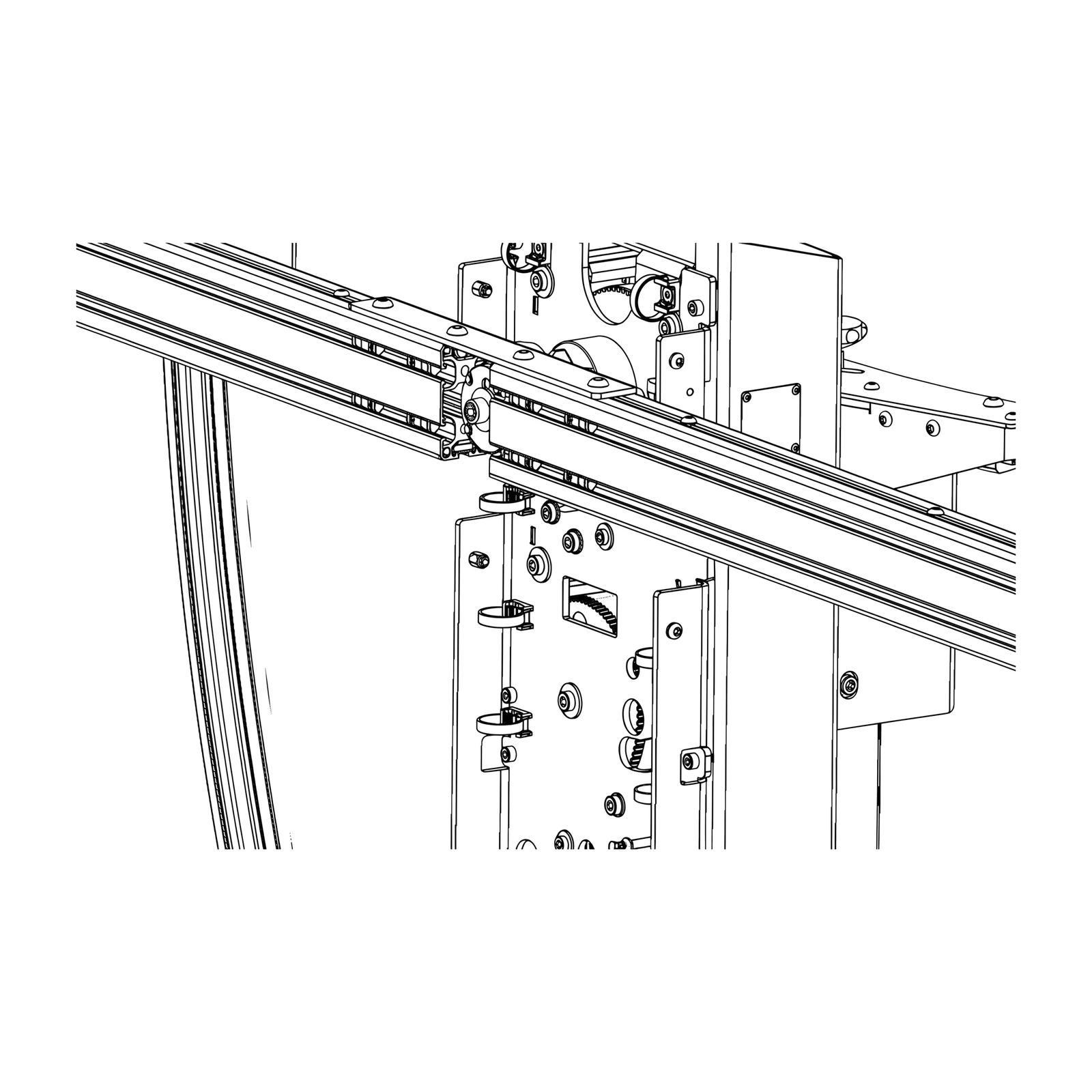
Checkpoint (geometry):
- Both sides of the front section are flush with the central axis, no gap.
- The arm is straight - not twisted. Sight along the arm from the front: front section parallel to the rear boom.
- All 12 screws tight; connecting parts tight on both sides.
- Shutter cable undamaged at both spindles.
Keep the support under the rear beam until the background is mounted (chapter 10).
07 Cabling and sheet-metal covers
Goal: every cable on the arm runs under the sheet-metal covers, so none is visible in the images and none can be caught when the arm swings.
7.1 Which cables run on the arm
| Cable | Route | Length |
|---|---|---|
| Front-left softbox power | front-left side of the arm | 5 m |
| Front-right softbox power | front-right side of the arm | 5 m |
| Rear-left background light power | rear-left side (older models) or the hole in the left sheet metal (newer models) | 5 m / 3 m |
| Rear-right background light power | rear-right side, or the hole in the right sheet metal (newer models) | 5 m / 3 m |
| Shutter cable (with coupler) | front-right side, from the spindle to the camera mount | factory-fitted |
| Front laser power | front-right side, to the laser under the camera mount | factory-fitted |
| Camera power, camera USB (active extension 10 m) | under the covers to the camera mount - plan this before closing the covers | - |
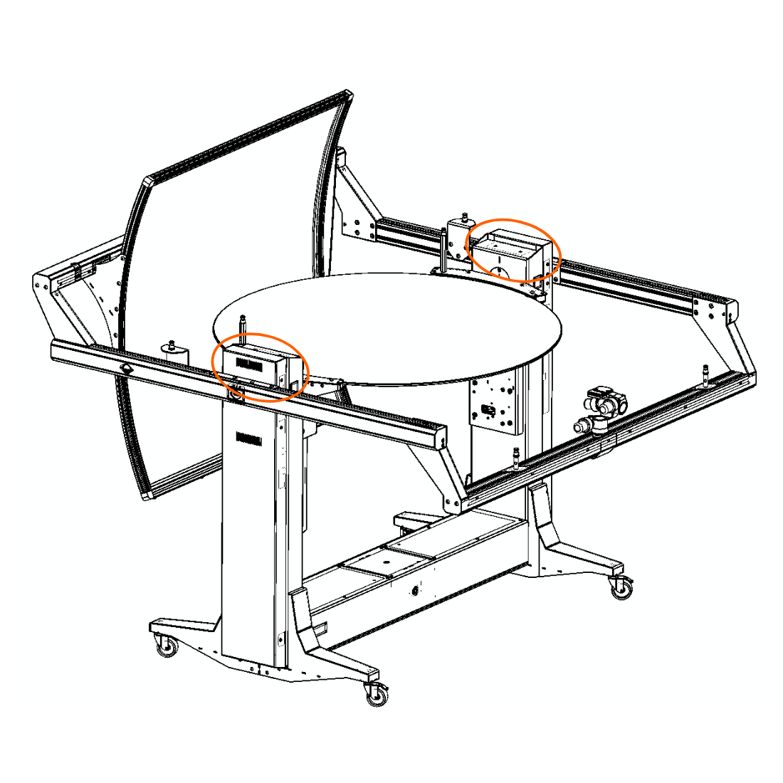
Step 7.2 - Mount the white side covers
- Mount the white cover on both sides of the machine.
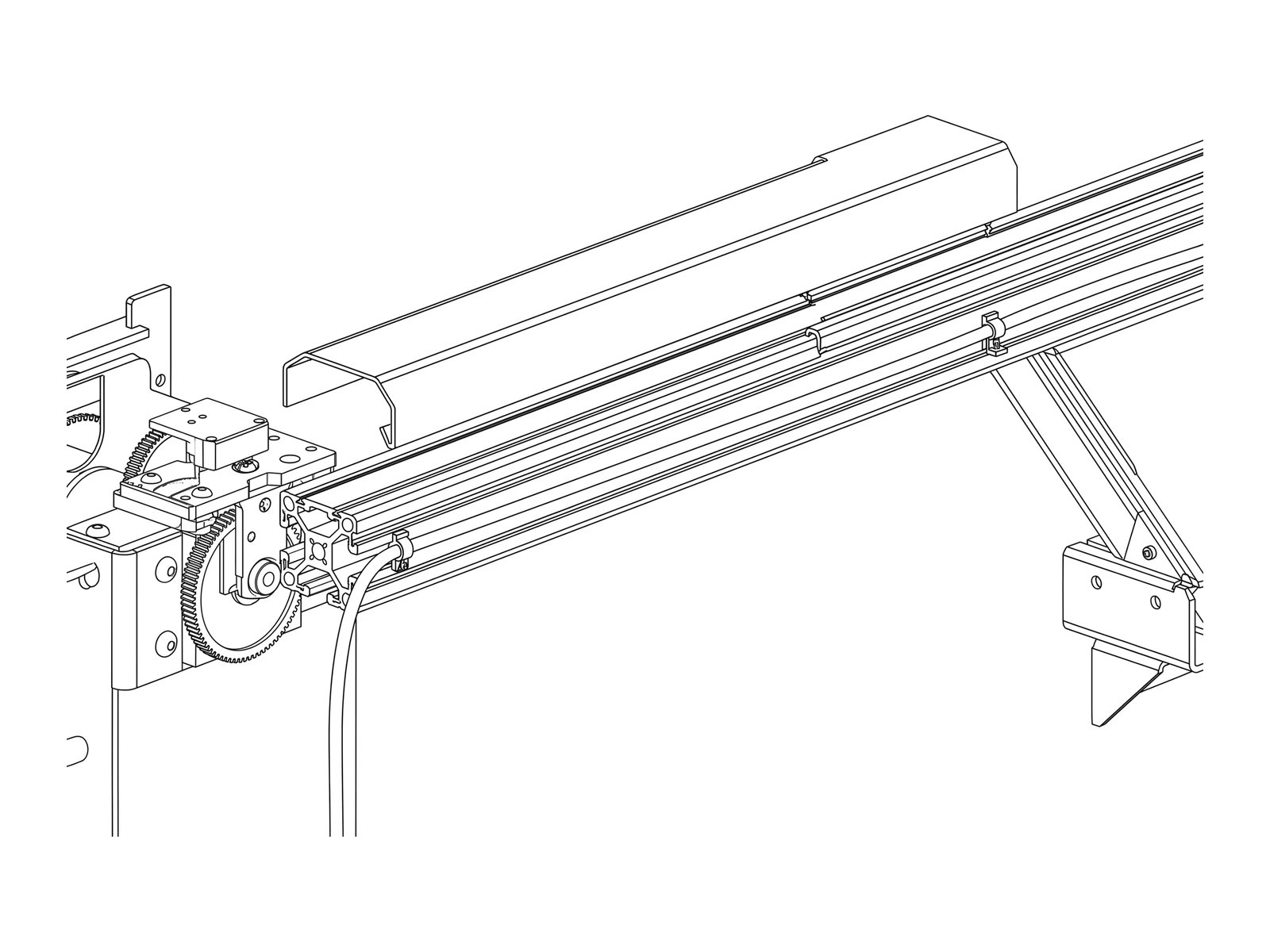
Step 7.3 - Route one light cable (repeat for each)
- Push the cable through the side of the swing arm (entry slot) to the light position.
- Lay it along the side of the aluminum profile.
- Place the sheet-metal cover over the cable and fasten 3 screws on the top side and 3 on the bottom side.
- Straighten the cable gently before you route the next one. No loops at the spindle - the arm must be able to swing from -60 deg to +90 deg without pulling any cable.
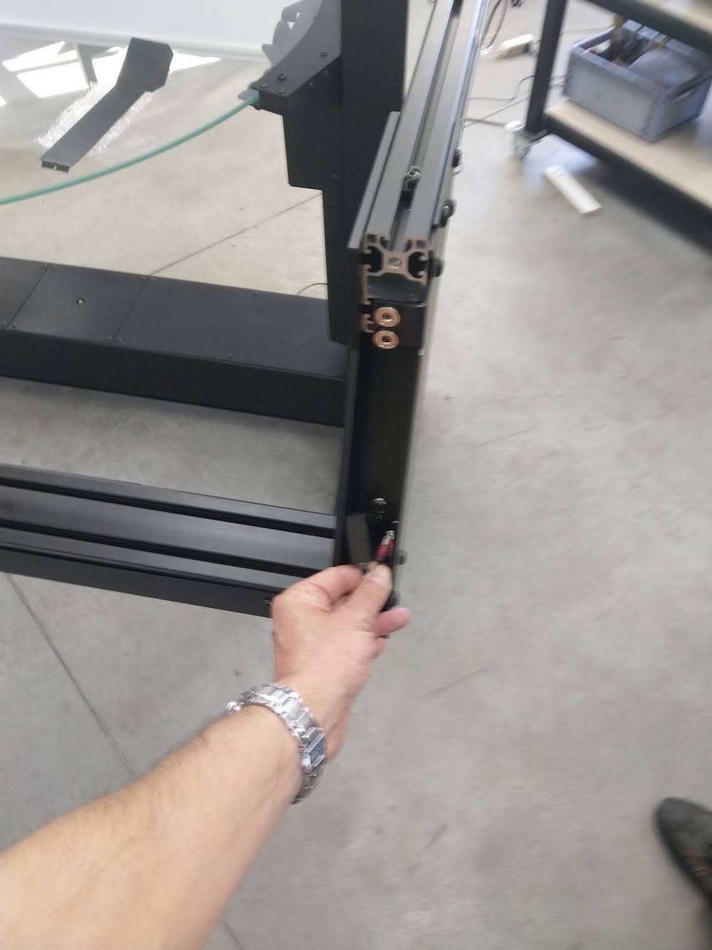
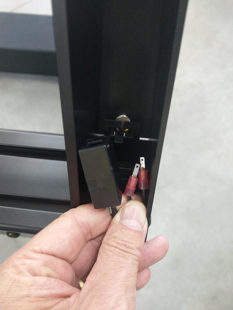
Step 7.4 - Right side: connect shutter and laser cables
The front-right side carries two factory-fitted cables with connectors: the shutter cable with coupler and the front laser power cable. Their counterparts are fastened near the central axle of the swing arm.
- Connect both pairs.
- Lay them along the power cable under the cover.
Step 7.5 - Covers on the uprights and the central hub
- The cables from the left and right side come out at the central plastic hub on the arm.
- On the left upright, between the upper and lower beam, a magnetic cover hides the cables that run from the top beam to the bottom beam.
Checkpoint:
- No cable visible from the camera position.
- Swing the arm by hand (supported, power off) through its full range: no cable pulls, rubs or pinches.
- Shutter and laser connectors joined and tucked under the cover.
08 T-slot nuts and light holders
8.1 Three kinds of T-slot nut
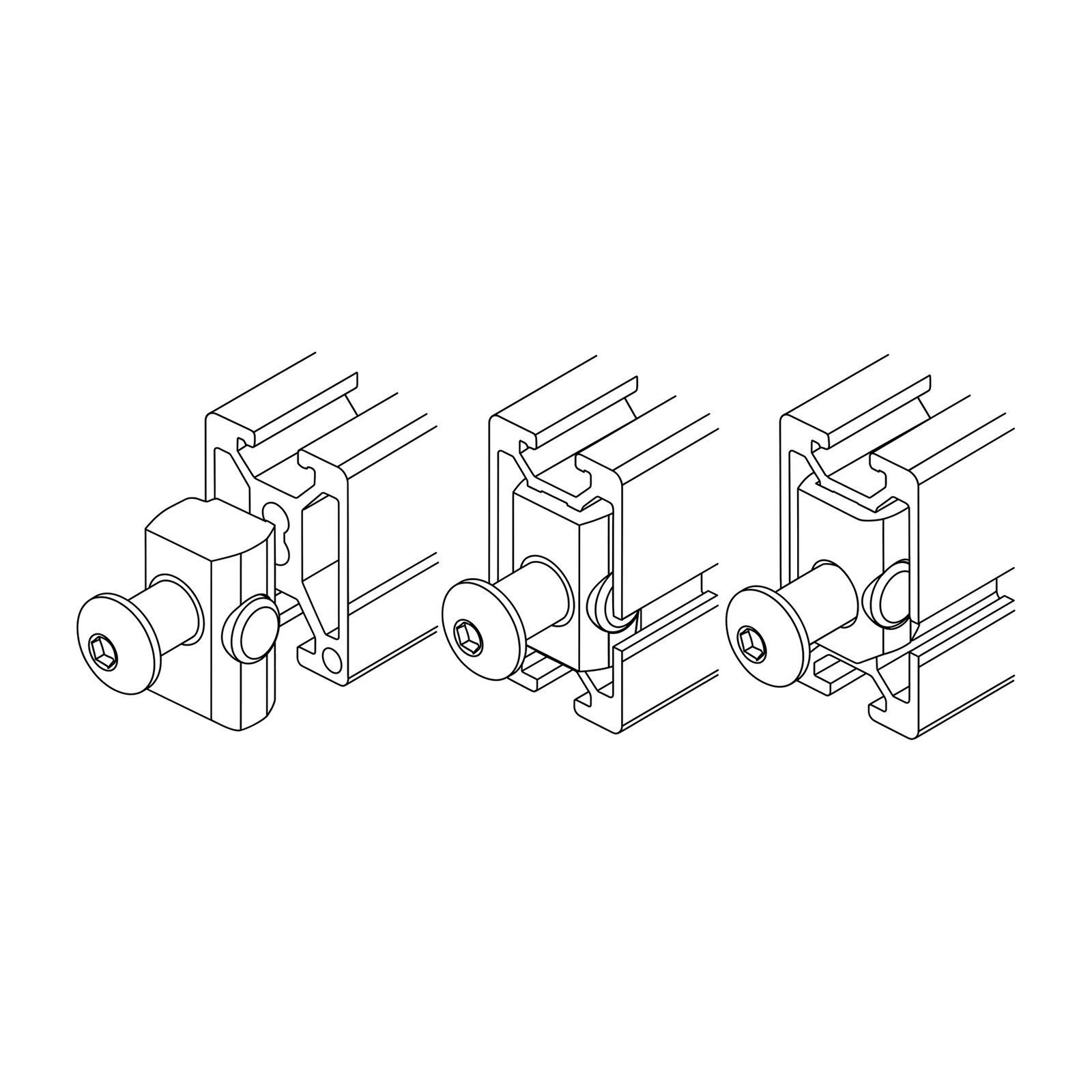
Everything that bolts onto an aluminum profile of the FRAME is fastened with a T-slot nut that sits in the slot of the profile. There are three kinds, and they are not interchangeable everywhere. Sort them into three labeled trays before you start.
| Type | What it looks like | Where it goes | Note |
|---|---|---|---|
| A - spring-ball nut | Dark body with a small spring-loaded ball on top (old manual image #41, "special pegs/stones") | Attachment points between assemblies on the arm - e.g. background side brackets to the rear boom, light holders | The ball holds the nut in place in the slot while you position the part |
| B - rectangular nut | Plain machined silver rectangle with a threaded hole, no ball | Inside the background frame profiles (curved X profiles and crossbars) | May replace A at some points, where PhotoRobot allows it |
| C - small nut | Smaller nut for a smaller screw | Sheet-metal cable covers on the arm | Small and easy to miss - check every small-parts bag |
Why it matters: if type A nuts are used inside the background frame, there are not enough left for the attachment points on the arm, and those points look as if parts were missing. Put each type where it belongs and replace wrongly used nuts - a wrong nut may let a part work loose and fall later.
PhotoRobot always packs a few more nuts than needed. Loose nuts can slide inside the profile slots and hide there - check the slots of the arm and the X profiles before you report a nut as missing.
8.2 Where T-slot nuts are used
| Location | Type | Qty | Chapter |
|---|---|---|---|
| Front section to swing arm, each side | (to be confirmed) | 2 rows x 3 = 6 per side | 06 |
| Front light holders | A | 4 | 8.4 below |
| Background frame, bottom edge of the X profile (black curtain) | B | 5 | 09 |
| Background frame, curved side profiles | B | 5 per side | 09 |
| Background side brackets to rear boom | A | (to be confirmed) | 10 |
| Sheet-metal cable covers | C | (to be confirmed) | 07 |
Step 8.3 - If a mounting point has a bolt but no nut
- Check that no type A nut was used inside the background frame (if so, see chapter 09, step 9.8).
- Check the small-parts bags and the profile slots of the arm and the X profiles - nuts slide and hide.
- Where PhotoRobot allows it, use a type B nut instead of type A .
- One missing nut inside the X profile is acceptable - the profile will still hold tightly. More than one: report to PhotoRobot.
- If type C nuts for the cable covers are missing, report to PhotoRobot with a photo; do not improvise with larger screws.
Step 8.4 - Mount the two front light holders
- Insert the 4 nuts (type A ) into the front section of the swing arm.
- Mount both front light holders onto them and tighten. Torque (to be confirmed).
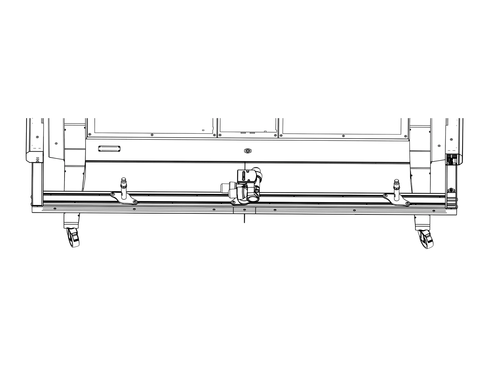
Checkpoint: each light holder sits flat and does not rotate when pushed by hand.
09 Background frame - assembly and squaring
If the background arrived assembled, skip to chapter 10. Depending on the crate size it may ship disassembled .
People: 2 - this is not a one-person job. One person holds tension on the textile and the profiles while the other fastens (PhotoRobot sends two technicians for this reason; one person alone needs much longer and the frame easily ends up bent and uneven). Time: about 1 h for two people. Work on a clean floor or a clean blanket - the white textile marks and tears easily; never stand or kneel on the frame or the fabric.
CAUTION - fastener type. Inside the background profiles use the rectangular nuts (type B), not the spring-ball nuts (type A) - see chapter 08. Type A nuts are needed later for the attachment points on the arm; using them here leaves you short and is the most common reason for "missing parts".
9.1 How the background is built
- A white textile with a sewn tunnel along its edges.
- A rubber cord threaded through the tunnel. The cord makes the edge thick enough to lock into the C-shaped slot of the profiles.
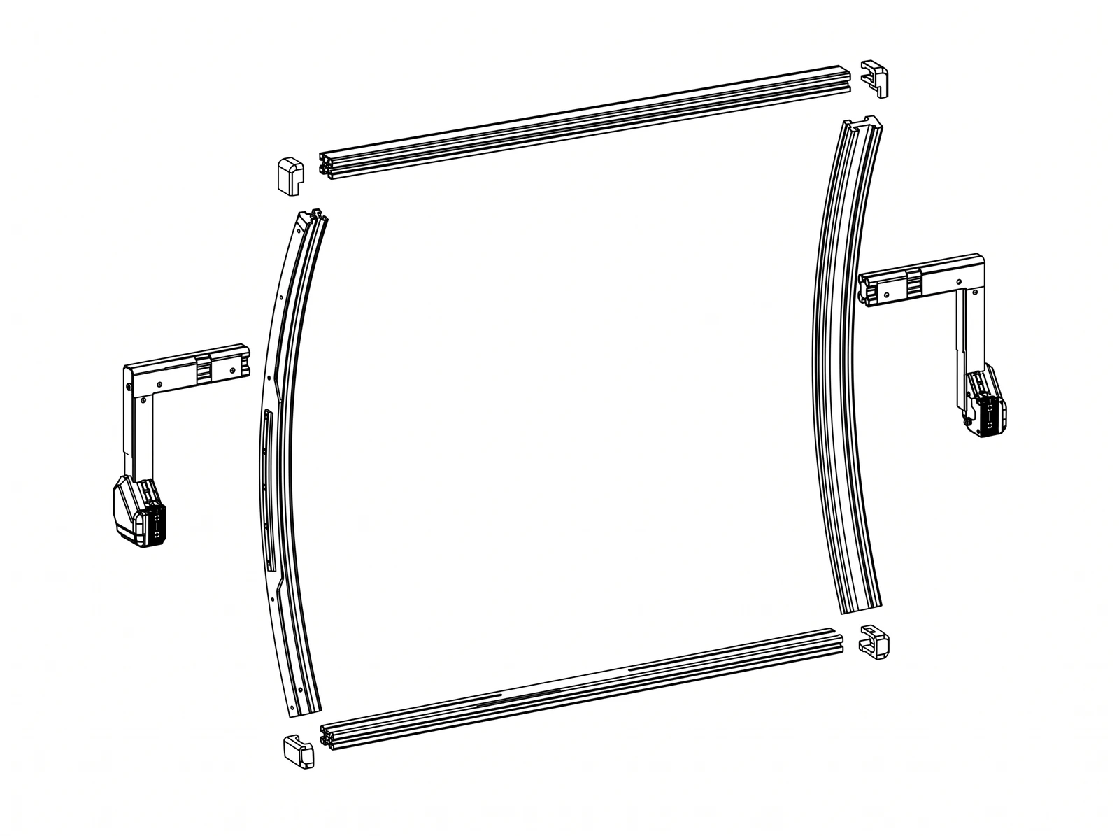
- Two curved "X" profiles (the sides) and two straight crossbars (top and bottom), joined at the corners with corner couplings.
- Side brackets that later hold the frame on the rear boom.
The textile is rectangular, not square - check the orientation before you start.
Step 9.2 - Thread the rubber cord into the textile
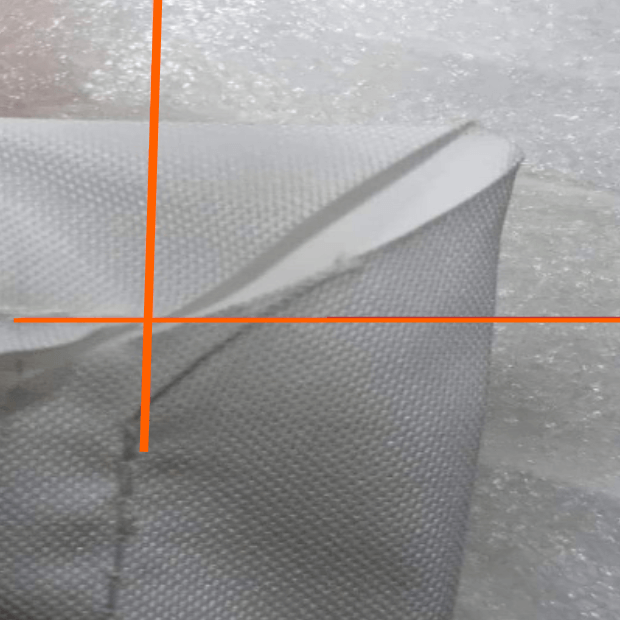
- Thread the rubber cord into the sewn tunnels of the textile.
- At the corners, shorten the cord as shown (cord ends meet at the corner seam, no overlap). Length: (to be confirmed).
Step 9.3 - Feed the textile into the curved side profiles (use the threading jig)
- Put the plastic threading jig on the end of the textile edge, with the cord inside.
- Push the jig into the C-shaped slot of the curved profile and pull it along; the jig guides the cord into the slot.
- Work along the whole edge. The cord must sit fully inside the slot along its entire length. A partly seated cord leaves the textile slack and the frame will feel loose later.
Step 9.4 - Form the "U" and insert the T-slot nuts
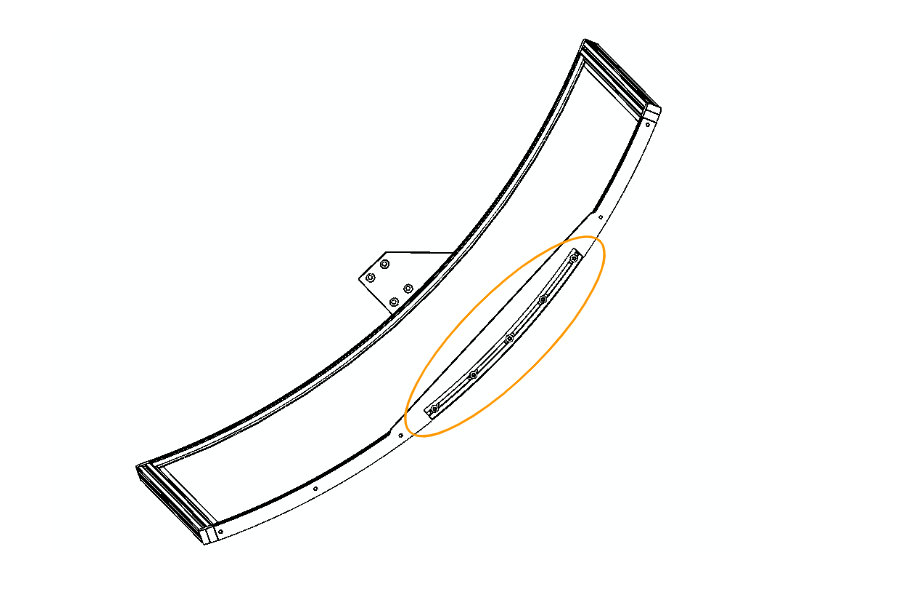
- Thread one straight crossbar into the bottom edge to form a "U" with the two curved profiles.
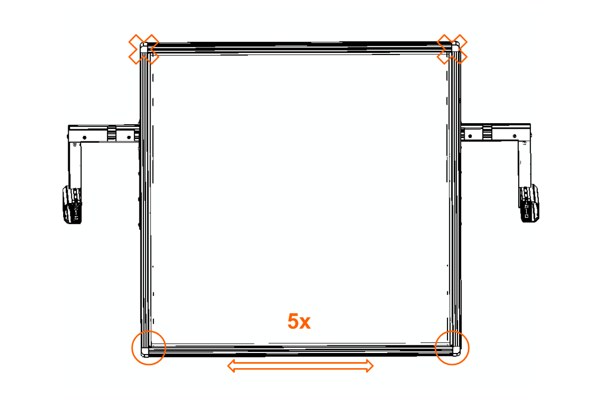
- Insert 5 rectangular T-slot nuts (type B) into the bottom edge of the X profile - they will hold the black curtain later.
- Insert 5 rectangular T-slot nuts (type B) into each curved side profile .
- If one nut is missing after a thorough search (including inside the profiles), the frame will still hold - one missing nut in the X profile is acceptable.
Step 9.5 - Join the corners
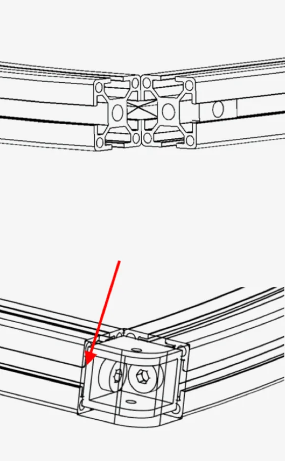
- Mount the corner couplings in the two bottom corners and connect the profiles.
- Thread the second straight crossbar into the top edge and join the top corners the same way.
- Tighten all corner couplings. Torque (to be confirmed).
X-shaped shims (only if needed)
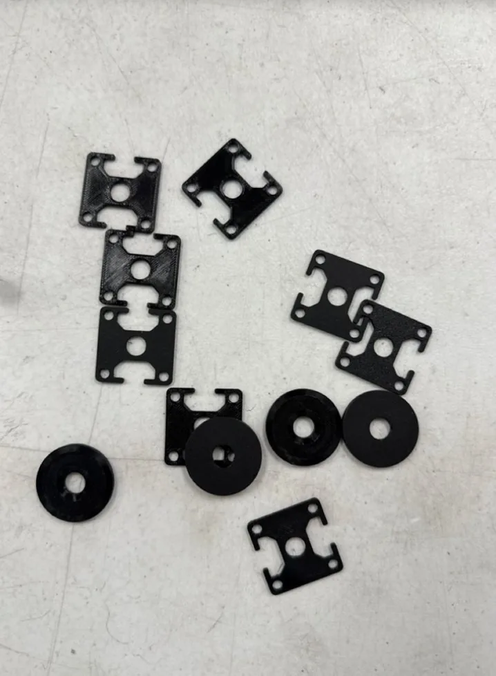
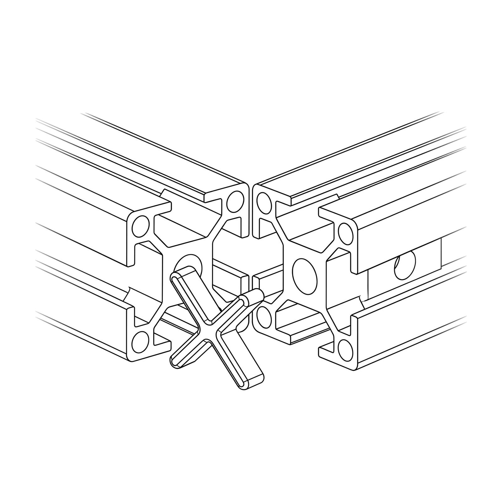
The background washer kit contains black, 3D-printed X-shaped shims - square plates with cut-outs that match the slots of the profile. If a corner does not close cleanly, the frame sits uneven, or the textile needs more tension, put one X-shaped shim between the end faces of the two profiles at that corner before you tighten the coupling.
The same kit also contains round black washers (about 3 cm, with a center hole). The FRAME does not use them - they are for the C1300 / C850 tables and are packed in the standard kit only to keep it simple. Set them aside.
Step 9.6 - Check squareness and tension
- Lay the frame flat. Measure both diagonals corner to corner. They must be equal within to be confirmed mm.
- Press the textile in the middle: it should be evenly taut with no wrinkles along the edges.
- Lift one corner a few centimeters: the frame should lift as one piece, without the corners opening.
If the frame is loose or out of square:
- check that the right nuts were used inside the profiles (type B) - if not, step 9.8;
- check that each corner coupling is fully inserted and tight;
- if a corner still does not close cleanly or the textile is slack, add an X-shaped shim at that corner (step 9.5);
- check the cord is fully seated along every edge (step 9.3);
- check the orientation (long edge vs short edge);
- check that the corner cord ends are shortened correctly (step 9.2).
Step 9.7 - Fit the side brackets
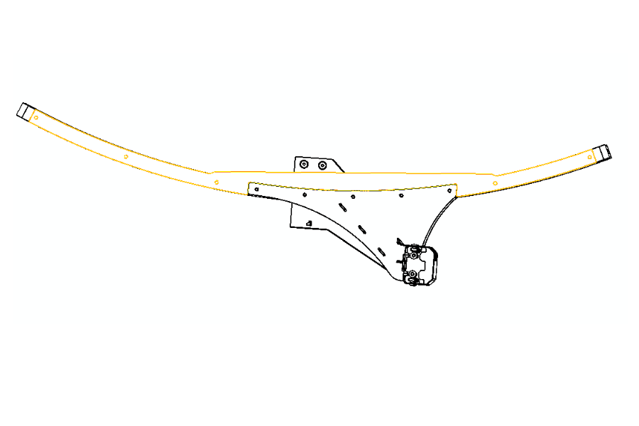
- Position the side brackets as shown in the template (blue in the old manual) and tighten them.
Step 9.8 - If the frame was assembled with the wrong nuts (rework)
Two people.
- Support the arm (chapter 04) - the background is part of its balance.
- Leave the curved side brackets attached to the arm. Remove the screws that hold the frame to the brackets and lift the frame off.
- Lay the frame flat on a clean blanket. Remove one straight crossbar, so the frame is a "U" again.
- Slide the spring-ball nuts (type A) out of the profiles and replace them with rectangular nuts (type B), on both sides.
- Refit the crossbar, re-check the corners and squareness (step 9.6), and mount the frame back on the brackets.
- Use the recovered type A nuts at the attachment points on the arm (chapter 08).
Handle the textile with care: the cord edge can tear where it was forced. Report any tears with a photo.
Checkpoint:
- Only type B nuts inside the background profiles.
- Diagonals equal within tolerance.
- Cord fully seated on all four edges, textile evenly taut.
- Corners closed and tight; frame lifts as one piece.
- 5 + 5 + 5 T-slot nuts in place; side brackets set to the template.
10 Mounting the background and the black curtain
People: 2. Before you start: front section mounted (chapter 06), rear beam still supported.
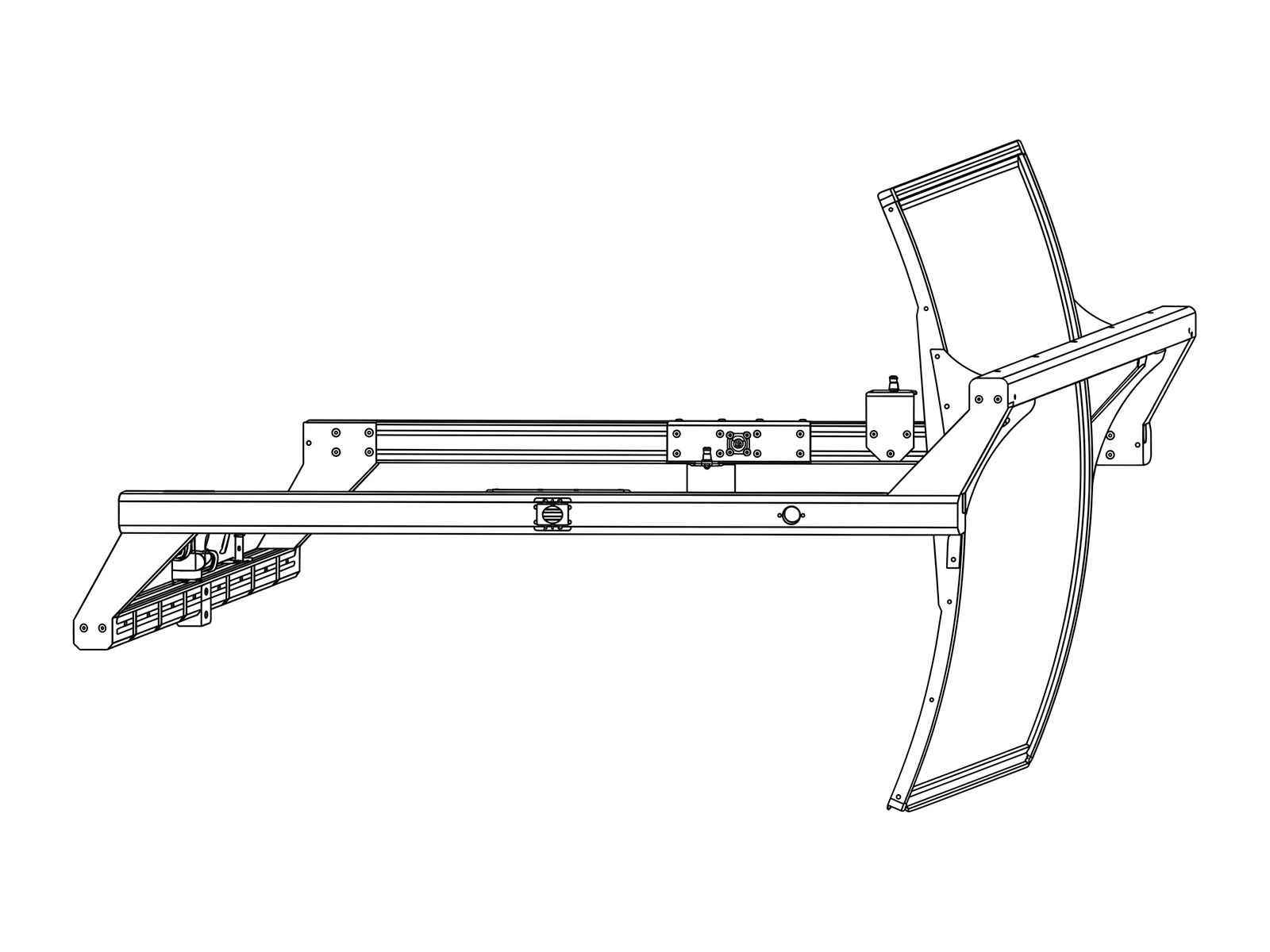
Step 10.1 - Put the background frame on the rear boom
- Insert the spring-ball T-slot nuts (type A, chapter 08) into the rear boom at the bracket positions - they go in from the front of the slot, no need to take anything apart .
- Lift the background frame (one person each side) and place it onto the rear boom with the side brackets over the nuts.
- Fasten the brackets to the nuts. Torque (to be confirmed).
WARNING With the background mounted and the camera not yet on, the rear end is heavier. Keep the support under the rear beam until step 10.3.
Step 10.2 - Mount the black curtain
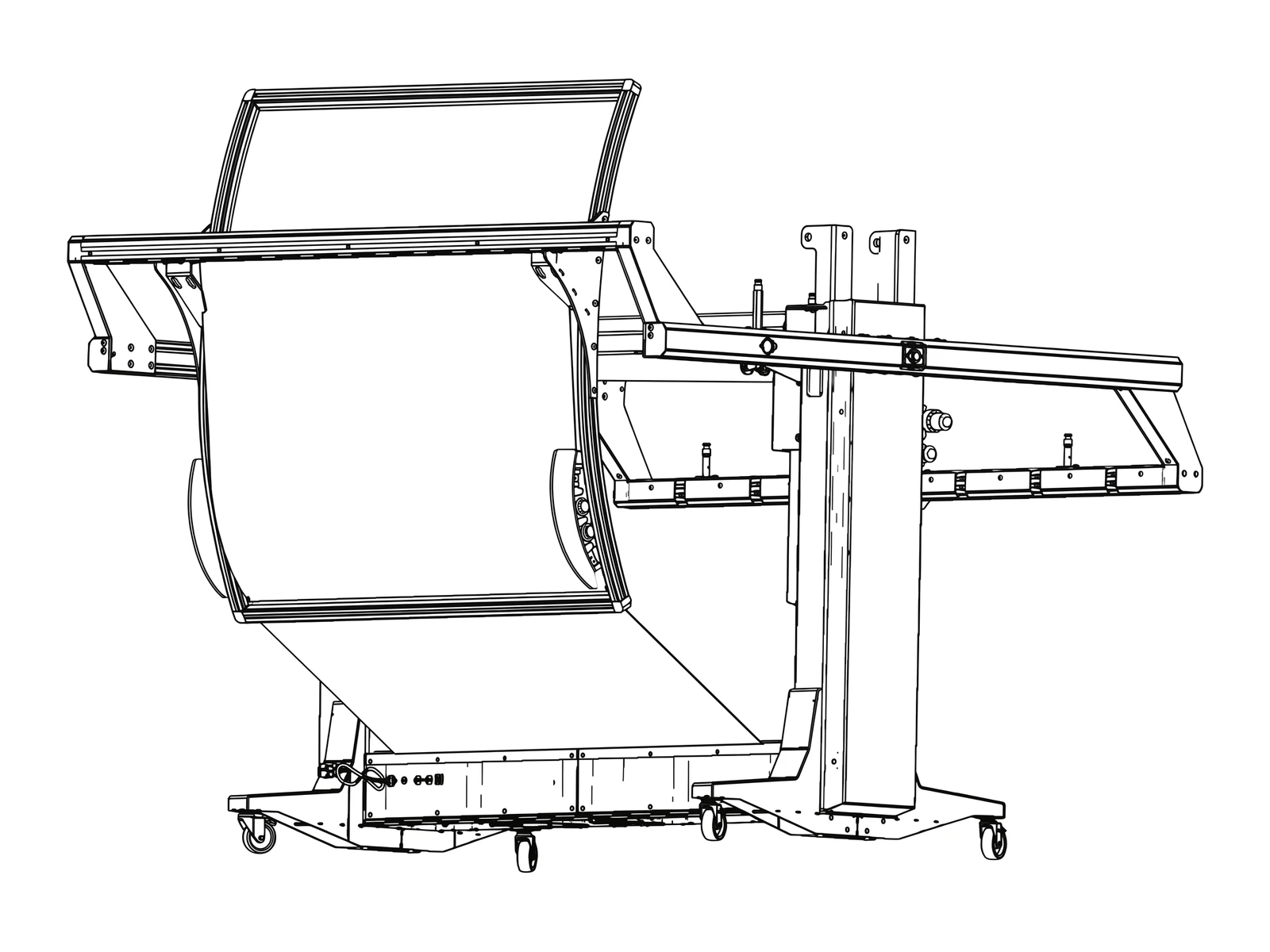
The black curtain (heavy black nylon foil) closes the gap between the bottom edge of the background and the lower part of the machine so that no light or floor shows through under the glass.
- Fix the top edge of the curtain to the 5 T-slot nuts in the bottom edge of the background X profile.
- Run the curtain down along the curtain line to the lower part of the machine and fix it there.
- It should hang smooth and slightly taut - no folds facing the camera.
Step 10.3 - Keep the support
Do not remove the support yet. With the background on and the camera and front lights still missing, the rear is much heavier than the front. The support comes off only after the camera and all four arm lights are mounted (chapter 04, step 4.3.6). Do not press Motor ON.
Checkpoint:
- Background sits square to the arm and does not wobble when touched.
- Curtain closes the gap, no folds visible from the camera position.
- Rear beam still supported; motors off.
11 Glass plate, camera and shutter cable
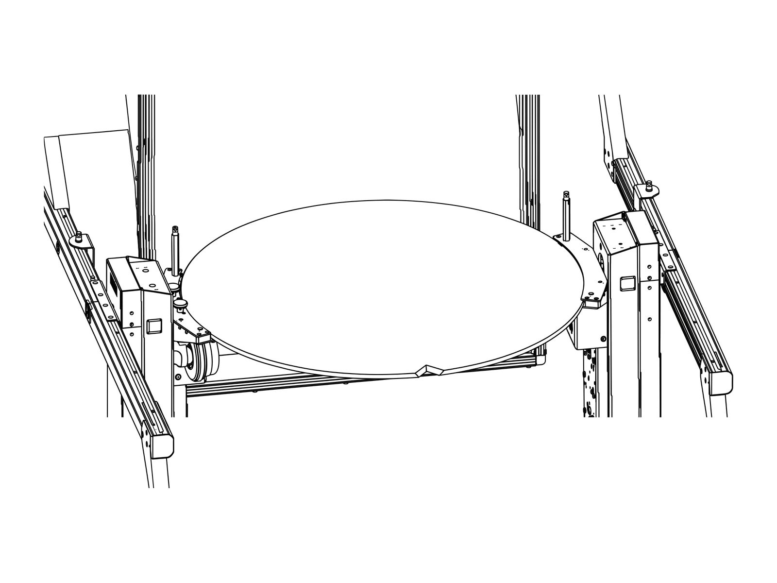
Step 11.1 - Place the glass plate
People: 2, with gloves. The plate is 1300 mm (51 in) in diameter.
- Clean the turntable rollers and the glass edge.
- Find the notch at the edge of the glass. The notch must face down.
- Lower the glass onto the turntable evenly, both people at the same time.
Checkpoint: the glass sits flat on all rollers and does not rock when pressed lightly at the edge. (The rotation test with the motors comes in chapter 13, after the gate check - .) If it rocks or later wobbles, lift it off and check the notch and the rollers. Do not shim the glass.
Step 11.2 - Mount the camera
- Mount the Manfrotto 405 geared head on the camera holder and the camera on the head.
- Route camera power and the active USB extension (10 m) under the covers (chapter 07) to the workstation.
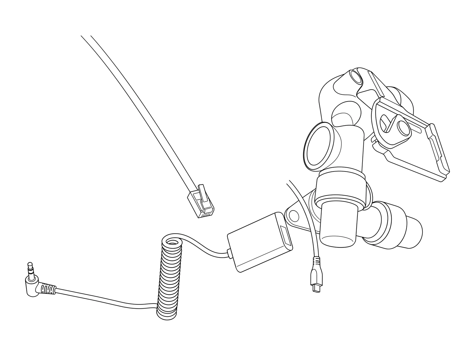
Step 11.3 - Connect the shutter cable
The shutter cable ends at the camera mount. Use the adapter set from the plastic bag:
- Canon N3 adapter, or 2.5 mm jack adapter, depending on the camera,
- plus 1 coupler.
- Connect the right adapter to the shutter cable via the coupler.
- Plug it into the camera's remote socket.
12 Mounting the lights and the light stands
This chapter covers only the mechanical part: getting all six lights onto the machine and the stands, so the arm is complete and balanced. Where each light goes, at which distance and angle, and the collision check are in the separate FRAME Light Setup manual. Follow it after chapter 13's gate check, when the arm may be moved electrically.
What the six lights are
Two background lights with reflectors and two product lights with softboxes on the arm; a top light on the boom stand LS-13B and a bottom light on the low floor stand LS-3B, both with 90 x 120 cm softboxes, standing in front of the machine. The bottom light is a floor light - it is not mounted under the glass. (Details: FRAME Light Setup.)
Step 12.1 - Find the stands
The boom stand LS-13B (with boom and counterweight) and the floor stand LS-3B ship in separate cardboard boxes on the pallet; the boom parts are wrapped in plastic foil; the lights are in a small cardboard box.
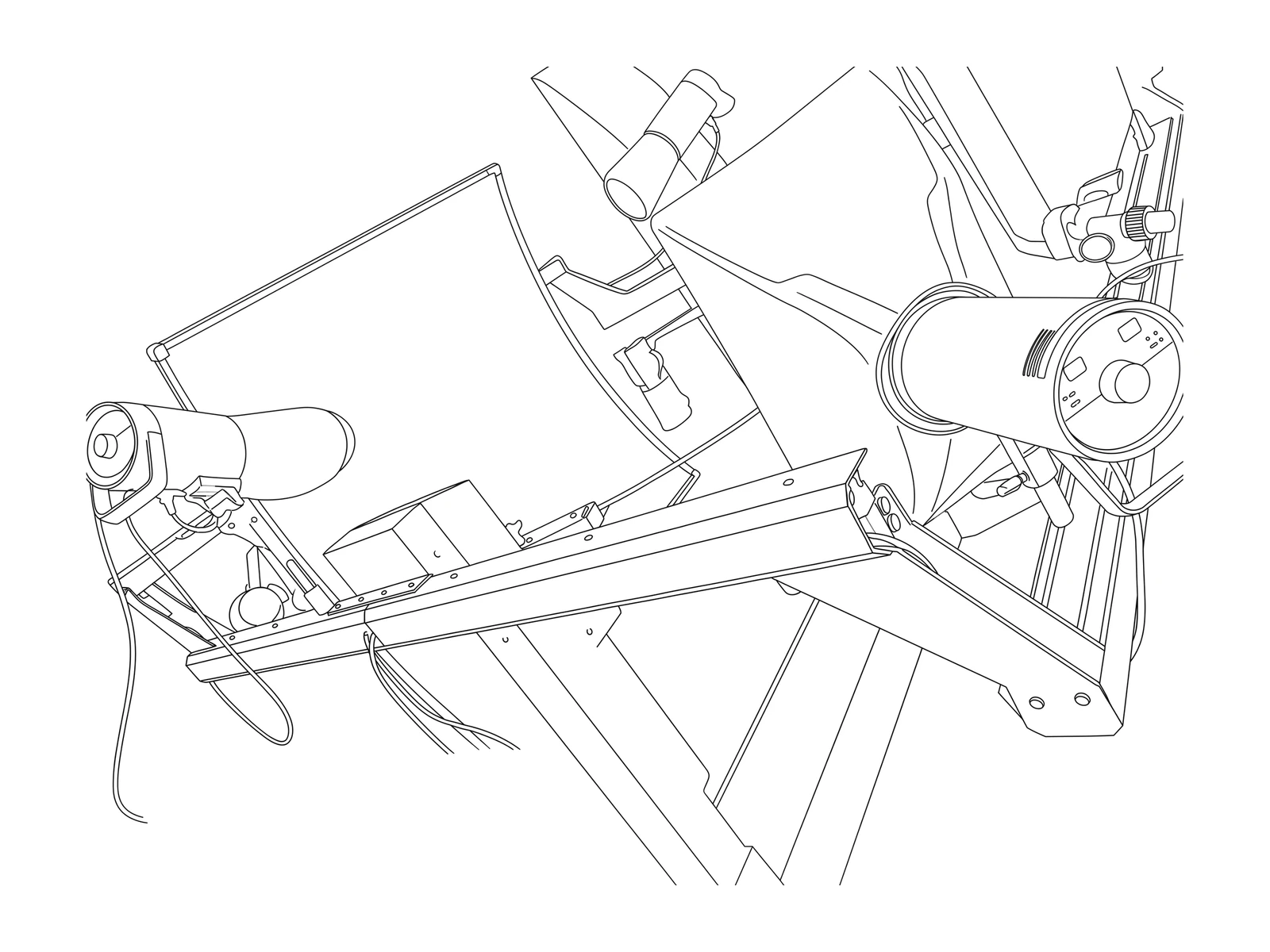
Step 12.2 - Mount the four arm lights (balance!)
- Background lights: on the rear boom, left and right, with their reflectors.
- Product lights: on the front light holders (chapter 08), with their softboxes in vertical position.
- Connect each light to its power cable routed under the covers (chapter 07).
- Mounting positions (34.5 cm / 21 cm) and aiming: FRAME Light Setup, sections 2 and 3.
After this step and the camera (chapter 11) the arm carries its full set - the condition for the first electrical movement in chapter 13.
Step 12.3 - Set up the two stands (no aiming yet)
- Assemble the boom stand LS-13B in front of the machine, outside the swing range of the arm. Mount the boom counterweight before you load the boom with the light. A loaded boom without counterweight can tip the stand into the machine or onto a person.
- Set up the floor stand LS-3B in front of the machine.
- Mount both lights with their 90 x 120 cm softboxes. Final position and the collision sweep: FRAME Light Setup, sections 4-6.
Step 12.4 - Power the lights
Spread the lights over separate circuits/phases - no more than two strobes per circuit . Strobes draw high current while recharging; on a shared or weak circuit they cannot recharge and fire at reduced power.
Checkpoint: four arm lights mounted and cabled; camera mounted (chapter 11); both stands assembled with the boom counterweight on. Continue with chapter 13, then the FRAME Light Setup manual.
13 Leveling check, laser alignment and final adjustment
Plan about 3 hours for this chapter. Laser alignment on a twisted or unlevel machine is impossible - always level first.
GATE - first electrical movement of the arm
Before the first Motor ON, confirm and tick:
- Camera mounted on its head on the camera holder.
- All four arm lights mounted: 2 rear (with cone shapers), 2 front (softboxes optional for balance).
- Background frame and black curtain mounted.
- Arm released from its support and stays roughly where it is left by hand.
- Nobody within the swing range of the arm; the top-light boom clears the arm.
If any box is not ticked, do not press Motor ON - the arm can drop and the machine can be damaged (chapter 04).
Step 13.1 - Re-check leveling with everything mounted
- With background, camera and lights mounted, check the level of the machine body again in both directions.
- Adjust the feet if needed. Target: (to be confirmed).
Step 13.2 - Find the center of rotation
Use the method in the Laser Centering & Alignment Guide:
- Put a round sticker at the approximate center of the glass.
- Mark the laser cross on it, rotate the glass 90 deg in the Service GUI, mark again; repeat to get four marks.
- Connect opposite marks: the intersection is the true center of rotation.
Step 13.3 - Align the FRAME lasers
The FRAME has 5 or 6 lasers:
| Laser | Location | Access |
|---|---|---|
| Front laser | under the camera, in the small cradle of the camera holder | camera holder |
| Top laser | at the top, under a cover (behind the logo area) | remove the cover |
| Left upright, vertical + horizontal | in slots on the inside of the left upright | remove the outer painted covers (upper and lower are separate pieces) |
| Right upright, vertical + horizontal | in slots on the inside of the right upright | same |
| Bottom laser | under the machine, below the central bottom cover | remove the central bottom cover |
- Remove the covers listed above. Handle the painted covers carefully and put them on a soft surface.
- From outside, adjust each laser with a 16-18 mm socket wrench until its line passes through the center of rotation found in 13.2.
- Refit all covers.
Step 13.4 - Calibrate and test in the Service GUI
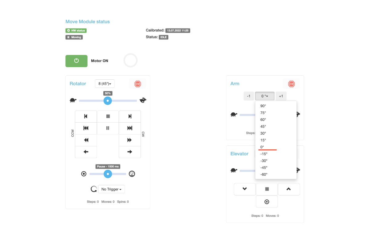
- Motor ON (first time only after the gate check at the start of this chapter). Move the arm to -60 deg, 0 deg, +45 deg and +90 deg. Movement must be smooth and quiet, and the arm must hold each position.
- Run the turntable calibration.
- Rotate the glass 360 deg at slow and full speed.
Acceptance: (to be confirmed)
- Machine level within to be confirmed.
- Laser lines meet at the center of rotation within to be confirmed mm.
- Glass run-out at the edge within to be confirmed mm; no wobble.
- Arm reaches -60 deg / 0 deg / +90 deg without noise; holds position.
- Turntable deviation per rotation <= 0.5 deg (spec).
- Lights positioned per the FRAME Light Setup manual, collision sweep 90 deg to -60 deg passed.
- Test spin from PhotoRobot Controls: 36 frames, all lights firing, background clean white, no cable visible.
14 Handover checklist
Complete with the customer's responsible person. Both sign the PhotoRobot handover protocol .
Machine
- All acceptance checks of chapter 13 passed; values written into the protocol.
- All covers fitted, all screws tight, no tools or packing left in or on the machine.
- Transport parts removed and handed to the customer for storage (or disposed of, as agreed).
- Machine serial number and control unit MAC written into the protocol.
Site
- Lights on separate circuits as planned; no travel adapters in use.
- Network per Networking Prerequisites; robot visible in PhotoRobot Controls.
- Overhead boom secured; walkway around the machine free.
Customer
- Customer knows how to switch the FRAME on and off in the right order and how to stop it.
- Customer has the links to this manual, Safety Information and Support.
- Customer knows how to open a support ticket and what information to include (photos, video, serial number).
- Training scheduled or completed.
PhotoRobot
- Photos of the finished installation (front 3/4, rear 3/4, each upright, cable covers) attached to the order.
- Open issues listed in the protocol with owner and date.
15 Troubleshooting
Steps marked [Technician] involve opening the machine or its electrical parts and are for PhotoRobot technicians only (see Safety Information). Customers: stop, take a video and open a support ticket.
| Symptom | Likely cause | What to do |
|---|---|---|
| A mounting point has a bolt but no nut | Spring-ball nuts (type A) used up inside the background frame, where rectangular nuts (type B) belong; or nuts hidden in the profile slots | Check the background for type A nuts and rework it (ch. 9.8); search the profile slots - PhotoRobot always packs spares. Type B may replace type A where PhotoRobot allows . (Ch. 08) |
| Small nuts for the cable covers missing | Type C nuts overlooked in the small-parts bags or not packed | Report with a photo; do not use larger screws. (Ch. 08) |
| One nut missing inside the X profile | Lost in transport or inside the profile | One missing nut is acceptable; more than one - report. (Ch. 08, 09) |
| Front section will not slide on | T-slot nuts out of line; one side pushed out while fitting the other | Two people, one per side, fit both sides together; align nuts with the holes first. (Ch. 06) |
| Arm swings rear-down when released by hand during assembly | Expected while the front section, camera or lights are missing - the arm is unbalanced | Keep it supported; finish the assembly in the order of ch. 04. Not a power-supply problem. |
| Arm dropped hard after Motor ON / "raise to 0 deg" | Arm moved electrically before the camera and all four lights were mounted (old manual 2.5 order) - motors have no brake | Stop, support the arm, mount the full set. Then check for damage: arm geometry, cables at the spindles, noise on a slow test movement. If in doubt: [Technician] inspection. (Ch. 04, 13) |
| Arm cannot hold position with everything mounted / moves weakly / new noise | Balance wrong (missing or extra weight); or a loose motor phase wire (48 V) after transport | Check that all parts are mounted (ch. 04). [Technician] with mains unplugged: remove the white side covers and the left and right bottom covers, check every wire in the connector blocks - pull each gently, re-tighten the screw terminal. A wire can sit outside the terminal while the screw is tight. |
| Customer suspects the power cord / 15 A adapter | Very unlikely: the FRAME draws well under 15 A at 115 V | Use a proper local power lead; do not chase cables. Look at balance and internal wiring instead. |
| Lights fire weakly or fail to recharge | Too many strobes on one circuit/phase, travel adapters, undervoltage | Max. two strobes per circuit; separate circuits; no adapters. (Ch. 12) |
| Background frame feels loose, bent or uneven after tightening | Wrong nuts inside the profiles (type A instead of B); assembled by one person without tension; corner needs an X-shaped shim; rubber cord not fully seated; corner couplings not fully inserted; wrong orientation; side brackets not set to the template | Rework with two people per ch. 9.8 (leave the side brackets on the arm, open one crossbar, swap the nuts), then re-check per ch. 9.6. Use the threading jig. If a corner still does not close or the textile stays slack, add an X-shaped shim between the profile end faces at that corner (ch. 9.5). |
| Leftover round black washers (about 3 cm) | They belong to the C1300/C850 tables; the standard washer kit includes them | Nothing to do - the FRAME does not use them. |
| Can't find the light stands / boom | The boom stand LS-13B and the floor stand LS-3B ship in separate cardboard boxes on the pallet, boom parts in plastic foil | Check the pallet around the crate before assuming parts are missing. (Ch. 12) |
| A light, reflector or the boom touches the arm | Lights not positioned per the FRAME Light Setup manual | Stop the arm; redo the positions and the 90 deg to -60 deg collision sweep (FRAME Light Setup, section 6). |
| Background wrinkles at the edges | Cord partly out of the slot; corner cord ends too long | Reseat the cord with the jig; shorten the corner ends (ch. 09). |
| Glass plate wobbles | Notch not facing down; dirt on rollers; machine not level | Lift the glass, clean, refit notch down; check leveling. Never shim the glass. If it persists: ticket (SUP-630). |
| Glass catches or runs off center | Machine not level or twisted; roller setup | Re-level first (an unlevel machine is the most common cause). If it persists: [Technician] roller/geometry adjustment - not possible remotely. |
| Laser lines do not meet at one point | Machine twisted or not level; lasers not adjusted | Level first, then align (ch. 13). If alignment is impossible, contact PhotoRobot - do not leave the machine in production with a misaligned laser without agreement. |
| Robot not found on the network | Customer network blocks discovery (proxy, isolation, no DHCP) | Follow Networking Prerequisites; use the PhotoRobot networking kit. |
| Camera does not fire | Wrong shutter adapter, coupler not connected, connector at the central axle not joined | Check the chain cable -> coupler -> adapter -> camera (ch. 11) and the front-right connector pair (ch. 07). |
| Shutter or laser dead after assembly | Cable pinched or cut at the spindle while moving the arm | [Technician] check the cable at the spindle exit; replace if damaged. |
When to stop and call PhotoRobot
- Any smell, smoke, sparking, or a damaged power cord: switch off, unplug, do not continue.
- Geometry, roller or laser problems that remain after leveling.
- Anything that needs opening the control electronics.
For machines installed by PhotoRobot, open a support ticket at https://support.photorobot.com with photos or a short video, the serial number and the firmware/Controls version. (Self-installed machines: see the installation policy in chapter 00.)
PhotoRobot Academy
Learn it in the PhotoRobot Academy
This manual is the reference. The Academy teaches the topic step by step, with exercises and a certificate.
- Module B02PhotoRobot SafetyOperator Standard
- Module H01PhotoRobot Hardware AnatomyHardware Specialist Essentials
- Module H02Installation & Handover VerificationHardware Specialist Essentials
- Module H03Maintenance, Replacement & Field TroubleshootingHardware Specialist Essentials